System for tracking railcars in a railroad environment

a technology of real-time computer system and railcar, which is applied in the direction of vehicle position/course/altitude control, process and machine control, instruments, etc., can solve the problems of inability to distinguish the number of railcars in a train by a system, the same number of wheels cannot be used in a train, and the number of railcars in a train is changing dynamically, so as to reduce the operational cost of coupling and accurate identification of railcars

Inactive Publication Date: 2007-06-28
MITSUBISHI ELECTRIC RES LAB INC
View PDF16 Cites 34 Cited by
  • Summary
  • Abstract
  • Description
  • Claims
  • Application Information

AI Technical Summary

Benefits of technology

[0011] Another embodiment of the invention provides a decision support method for yard and depot operation using dynamic railcar allocation and scheduling. The method uses the real-time coupling information to allocate a block of coupled railcars to a train and to reduce operational cost of the coupling and uncoupling operations.
[0012] Another embodiment of the invention provides more accurate identification of railcars in a railroad environment where many AEI readers are close to each other because the tracks are spaced relatively close. The AEI readers are combined with optical components, such as infrared readers or cameras, and photo emitters. This way, a particular AEI reader can be activated by the optical components when the railcar is on a selected track.

Problems solved by technology

In general, it is known that pattern recognition is less accurate and less reliable for moving objects under changing lighting conditions.
However, trains with the same number of wheels cannot be distinguished by that system.
This is a particular problem in a rail yard or train depot where most trains are either relatively short, e.g., a single railcar, or the number of railcars in a train is changing dynamically.
Because the railcar is not identified specifically, incorrect information can be collected.
The on-board system requires a power source and maintenance, increasing the cost of the system.

Method used


Image

  • System for tracking railcars in a railroad environment
  • System for tracking railcars in a railroad environment
  • System for tracking railcars in a railroad environment

Examples


Embodiment Construction

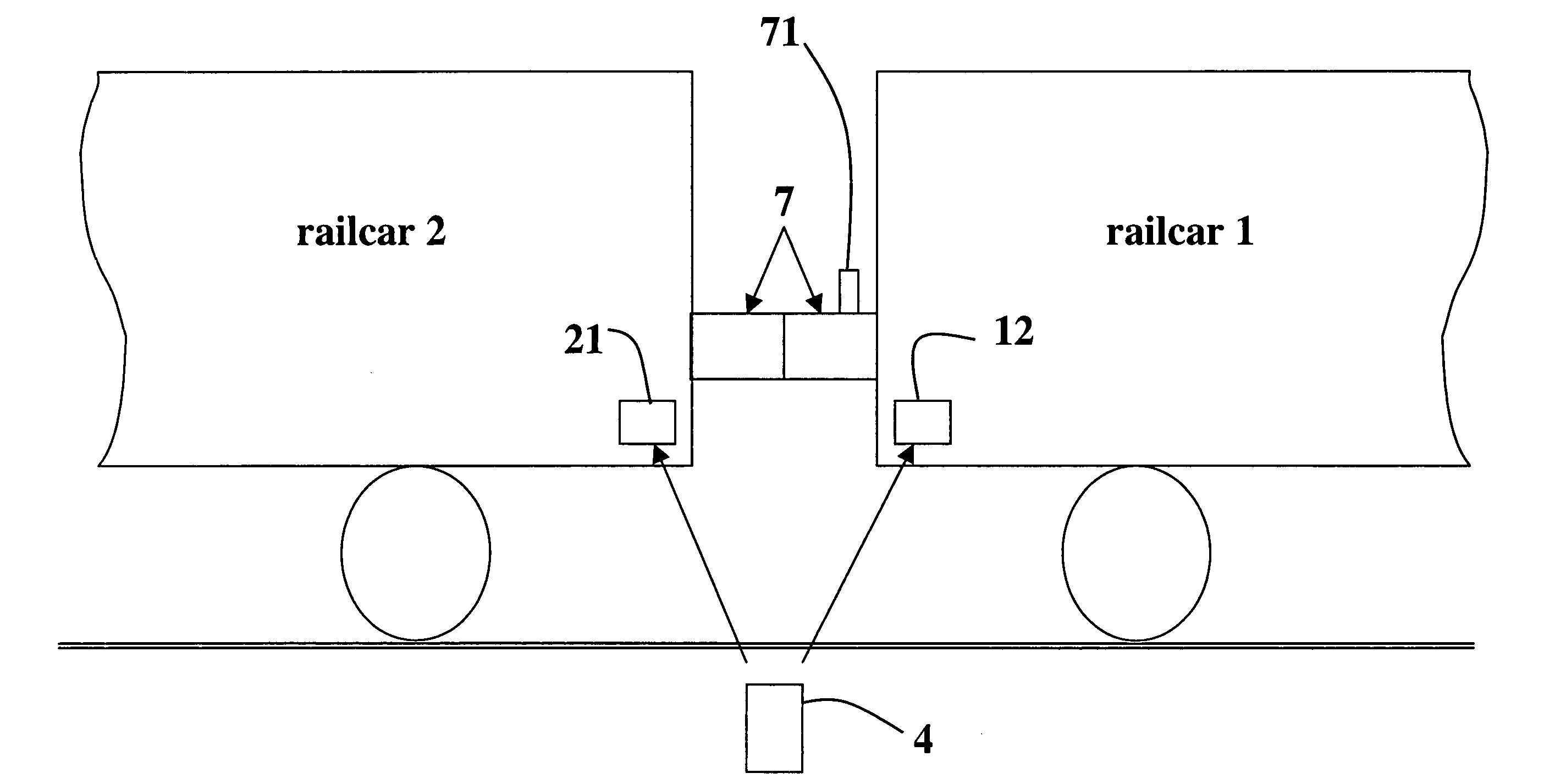
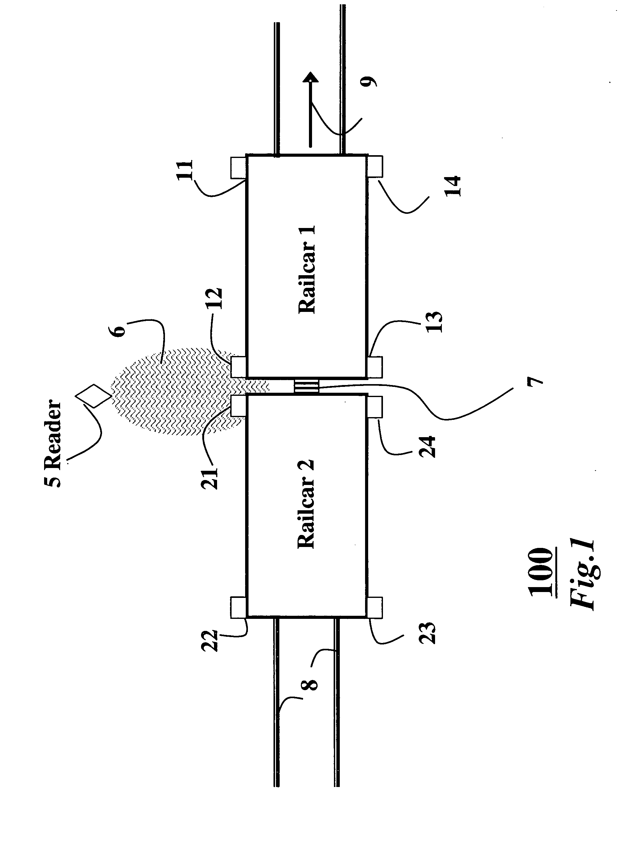
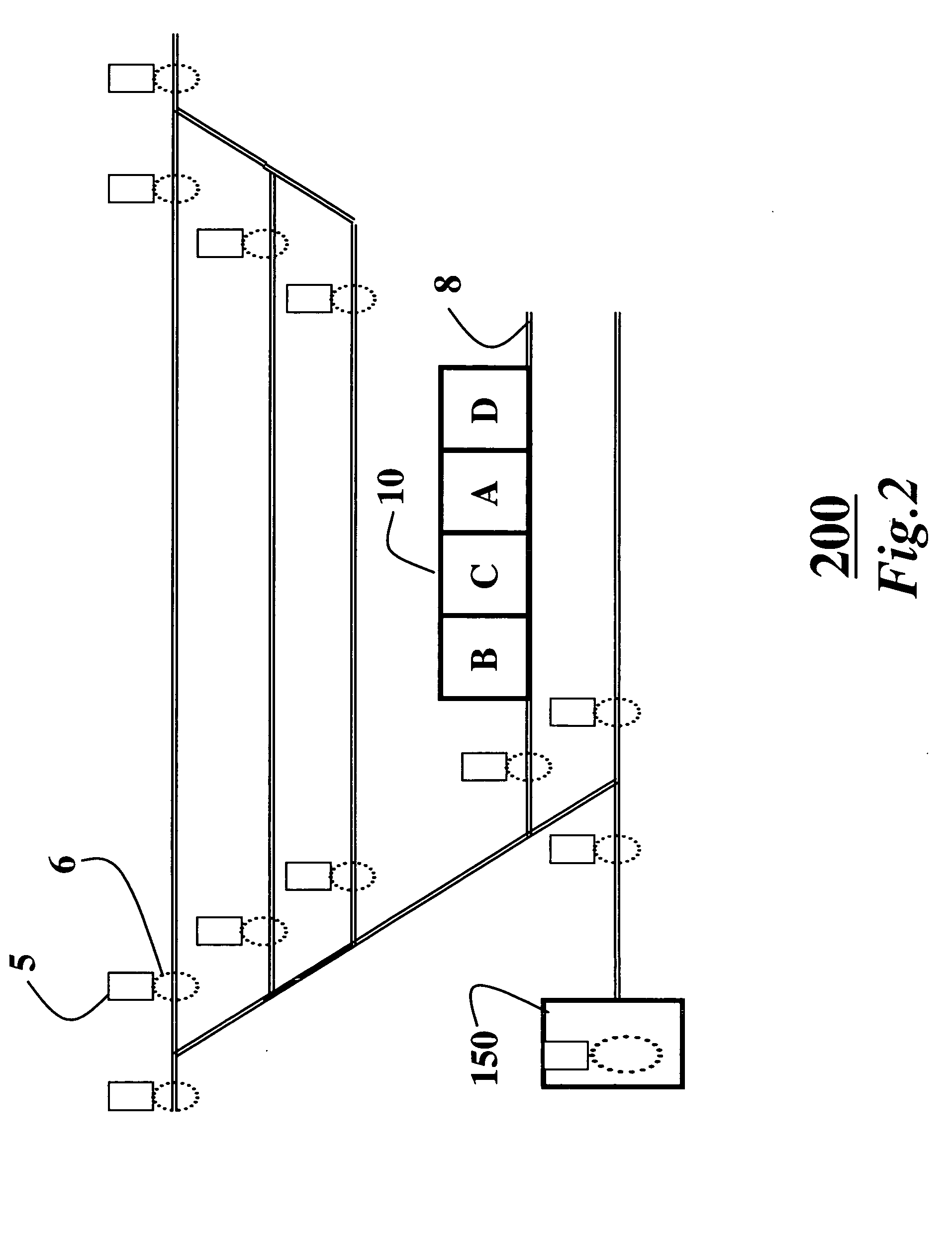
[0018]FIG. 1 shows a small portion 100 of a railroad environment, e.g., a rail yard or train depot. The environment includes an automated equipment identification (AEI) reader 5, AEI RFID tags 11-14 attached to a railcar 1, and AEI RFID tags 21-24 attached to a railcar 2. Every RFID tag includes a unique identification (ID) that can be read by the AEI reader 5. The RFID tags are placed near the corners of the railcars, e.g., on the sides and near the ends of the railcars. Multiple RFID tags are used to increase reliability of reading the RFID tags.

[0019] The AEI reader 5 is located adjacent to a track 8. The reader uses radio frequency (RF) signals 6. A range and direction of the RF signals 6 is adjusted so that the reader 5 can only read one RFID tag at a time, unless two adjacent railcars are coupled by a coupler 7. In this case, the reader 5 can concurrently read only two RFID tags on abutting comers of the two coupled railcars. When the railcars 1-2 move on the track in a parti...


PUM


Abstract

A system determines real-time locations of railcars in a railroad environment. Railcars are equipped with at least four RFID tags. A RFID reader at a fixed location at every track branch in the environment reads the RFID tags. Railcar locations are updated for the railcars by determining the branches on which the railcars are located.

Description

FIELD OF THE INVENTION [0001] This invention relates generally to tracking railcars, and more particularly to real-time computer systems for tracking railcars in a rail yards and train depots. BACKGROUND OF THE INVENTION [0002] Rail yards and train depots perform important services such as freight distribution, railcar interchange and termination, and railcar inspection and maintenance. Therefore, management of railcars in the yards and depots is important for efficient railroad operation. Therefore, there is a need for a system that can provide real-time information on the location and status of railcars in the yards and depots. [0003] U.S. Pat. No. 6,637,703 describes a system for tracking railcars by using an automated equipment identification (AEI) reader, which is also called as radio frequency identification (RFID) reader, and elevated cameras. Railcars in a yard are tracked by recognizing patterns in video images acquired by the cameras, and signals acquired by the readers. I...

Claims


Application Information

Patent Timeline
Patent Type & Authority Applications(United States)
IPC IPC(8): H04Q5/22G08B5/22
CPCB61L25/025B61L25/045B61L2205/04G06K2017/0045B61L25/048
Inventor KATO, MAMORUDIVAKARAN, AJAY
Owner MITSUBISHI ELECTRIC RES LAB INC
Why Eureka
Try Eureka