Method for generating calibration curve

a calibration curve and calibration method technology, applied in the field of generating calibration curves, can solve the problems of dragging the speed and performance of an image scanner, the above mentioned calibration method has some troubling drawbacks, and the linear image sensor such as ccd will not be identical, so as to achieve the effect of generating a calibration curve with high efficiency and performan

Inactive Publication Date: 2007-06-28
INTELLECTUAL VENTURES I LLC
View PDF3 Cites 0 Cited by
  • Summary
  • Abstract
  • Description
  • Claims
  • Application Information

AI Technical Summary

Benefits of technology

[0010] It is another object of this invention to provide a method for generating a calibration curve with high efficiency and performance.

Problems solved by technology

Moreover, linear image sensors such as CCD will not be identical and always respond differently to the same light signal.
However, the above mentioned calibration method has some troubling drawbacks.
It is apparently that such huge data quantity to be processed would drag the speed and performance of an image scanner.

Method used


Image

  • Method for generating calibration curve
  • Method for generating calibration curve
  • Method for generating calibration curve

Examples


Embodiment Construction

[0019] It is to be understood and appreciated that the method described below do not cover a complete system and method. The present invention can be practiced in conjunction with various software and hardware that are used in the art, and only so much of the commonly practiced components and steps are included herein as are necessary to provide an understanding of the present invention.

[0020] The present invention will be described in detail with reference to the accompanying drawings. It should be noted that the drawings are in greatly simplified form.

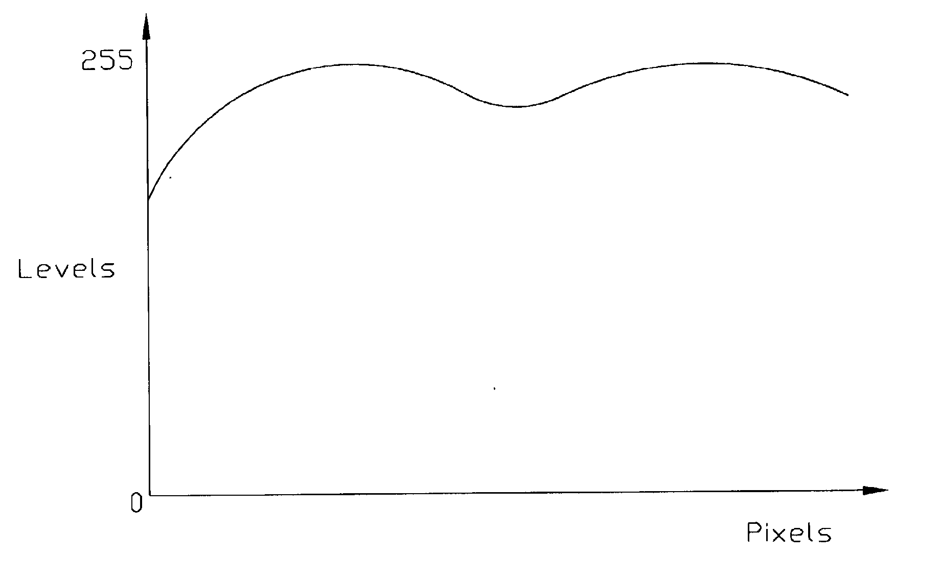
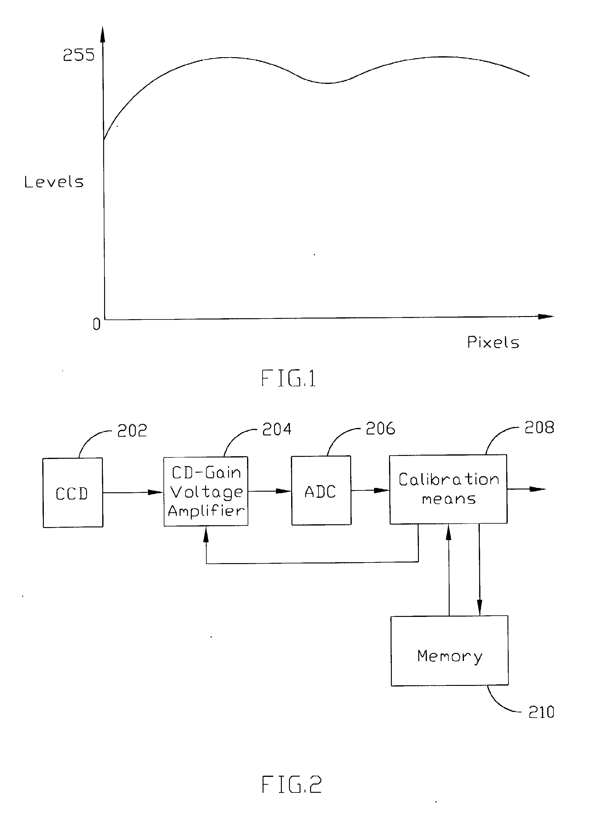
[0021] Referring to FIG. 1, a calibration curve how the bright levels of the generated image vary with pixel positions of one image line is shown. This curve is generated by scanning a total white calibration board to generate calibration data corresponding to each image sensors or CCD before scanning images formally. Normally, a calibration curve used to calibrate images is generated by selecting data of a plurality of image lines...


PUM


Abstract

A method for generating a calibration curve is disclosed. The method comprises the following steps. Calibration data of one line image of a previous scan are first provided. Reference pixels are selected from the image line. Then a calibration board is scanned and calibration data of the reference pixels are generated. Calibration data of the reference pixels of a previous scan are then selected from the calibration data of one image line of a previous scan. Ratios of the calibration data of the reference pixels and the calibration data of the reference pixels of a previous scan are calculated. Calibration data of all pixels of the image line are finally generated by multiplying the calibration data of the image line of a previous scan and the ratios.

Description

BACKGROUND OF THE INVENTION [0001] 1. Field of the Invention [0002] The present invention relates to a method for generating a calibration curve, and more particularly to a method for generating a calibration curve by selecting reference points of one image line instead of all points. [0003] 2. Description of the Related Art [0004] Optical scanners are used to capture and digitize images. For example, an optical scanner can be used to capture the image of printed matter on a sheet of paper. The digitized image can then be electronically stored and / or processed with character recognition software to produce ASCII text. The typical optical scanner includes a light source, a linear array of photoelectric sensing elements (generally a CCD sensor or a CMOS sensor, or a CIS sensor), an analog amplifier, an analog to digital converter (ADC), a controller and a random access memory (RAM). [0005] The CCD sensor includes a large number (e.g., 2000) of photoelectric sensing elements arranged i...

Claims


Application Information

Patent Timeline
Patent Type & Authority Applications(United States)
IPC IPC(8): G06F15/00H04N1/401
CPCH04N1/401
Inventor CHIU, CHUI-KUEI
Owner INTELLECTUAL VENTURES I LLC
Why Eureka
Try Eureka