Generating a scan pattern over multiple surfaces of symbol-bearing objects passing through flat bed reader

a flat bed reader and scan pattern technology, applied in the field of flat bed readers for electrooptically reading indicia, can solve the problems of unsuitable applications and unjustified high cost, and achieve the effect of increasing productivity and increasing productivity

Inactive Publication Date: 2005-04-07
SYMBOL TECH INC
View PDF6 Cites 2 Cited by
  • Summary
  • Abstract
  • Description
  • Claims
  • Application Information

AI Technical Summary

Benefits of technology

[0014] In accordance with the invention, a rotary mirrored component is rotatable about an axis, and a plurality of stationary, folding mirrors is arranged about the axis. A light source, preferably a laser, generates and directs a light beam to the rotary component for reflection therefrom to the stationary mirrors for reflection therefrom through the window to multiple surfaces of each object. A drive, for example, a motor, rotates the rotary component to sweep the light beam across the stationary mirrors and form a scan pattern of scan lines at and past the window and onto the multiple surfaces of each object. At least one of the stationary mirrors is located behind the rotary component, as considered downstream of the advancement direction, for reflecting at least one of the scan lines at a trailing surface of each object. Hence, this invention provides increased productivity by having the capability to read indicia even if the indicia are located on the trailing surface of the object.
[0015] Preferably, the stationary mirrors are arranged to sweep scan lines over each upright surface of the object, as well as over the bottom surface of the object. The scan lines are sloped and positioned to read symbols in the picket fence orientation, or the ladder orientation, or any orientation inclined therebetween. Symbols of any orientation can thus be read at every side of the object, except the top surface. The operator can easily be trained to grip the object near its top as the object is advanced through the workstation, thereby exposing all the other surfaces to the scan lines projected through the single window, and increases productivity in much the same way as the larger, more expensive dual-window readers.

Problems solved by technology

As advantageous as the dual-window readers are, their large size and high cost make them unsuitable for applications where there is insufficient room available to accommodate the extra window, and where the high cost is unjustified.

Method used


Image

  • Generating a scan pattern over multiple surfaces of symbol-bearing objects passing through flat bed reader
  • Generating a scan pattern over multiple surfaces of symbol-bearing objects passing through flat bed reader
  • Generating a scan pattern over multiple surfaces of symbol-bearing objects passing through flat bed reader

Examples


Embodiment Construction

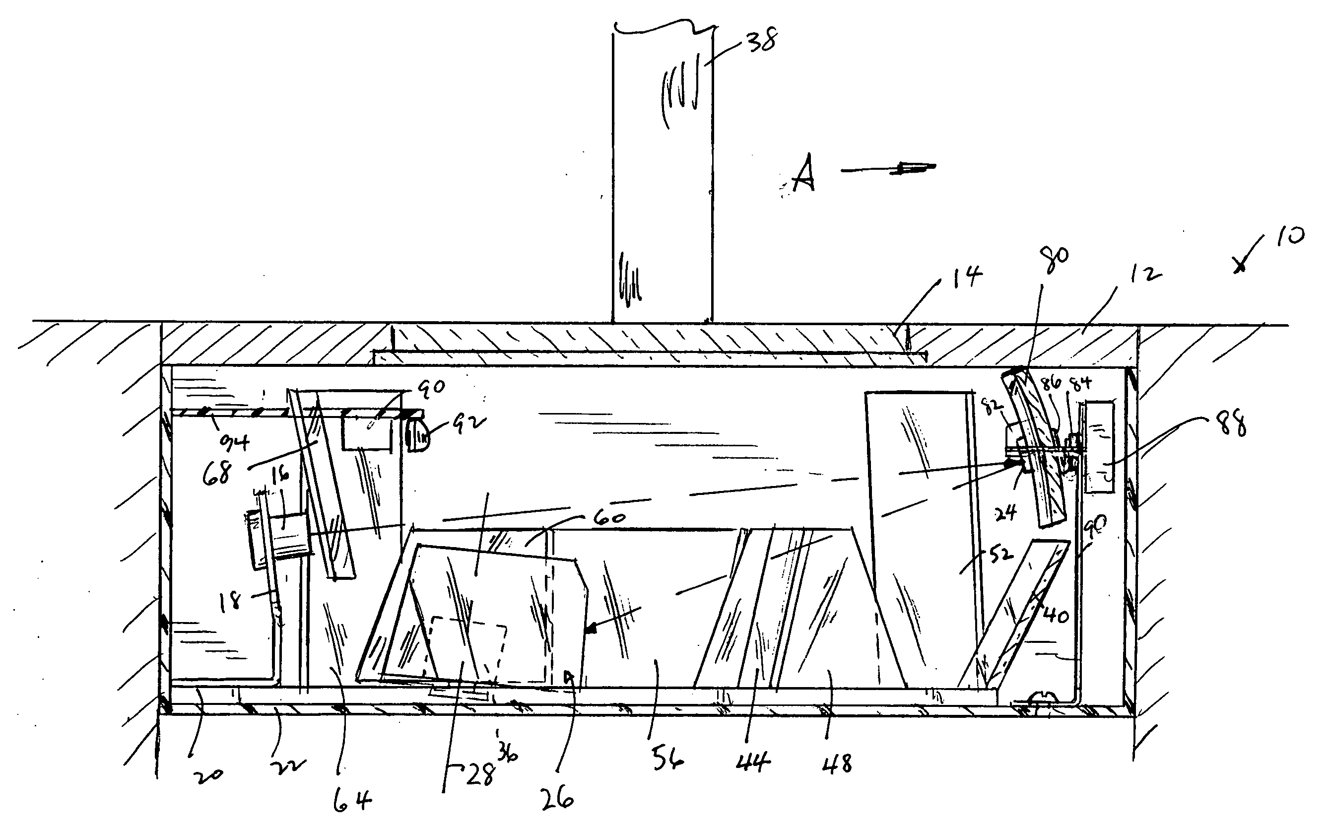
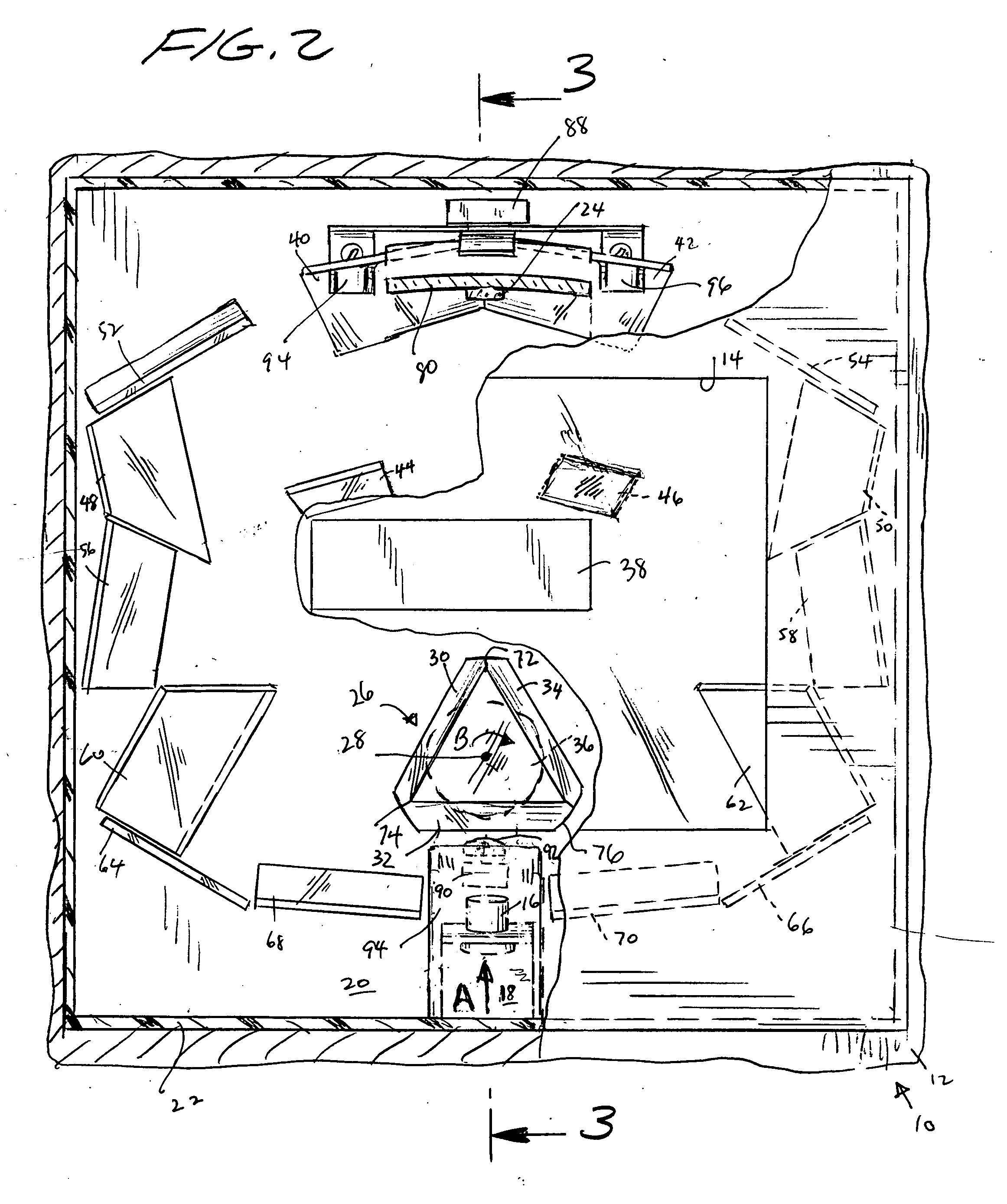
[0020] Reference numeral 10 generally identifies a workstation, as seen from overhead, for processing transactions and specifically a checkout counter at a retail site at which products, for example, a box 38 containing a foodstuff, are processed for purchase. Each product bears a bar code symbol. The counter includes a countertop 12 across which the products 38 are slid in an advancement direction, as indicated by the arrow A, over and past a horizontal window 14 set flush with, and built into, the countertop 12 of a horizontal slot scanner. A checkout clerk or operator is located at one side of the countertop, for advancing the products 38.

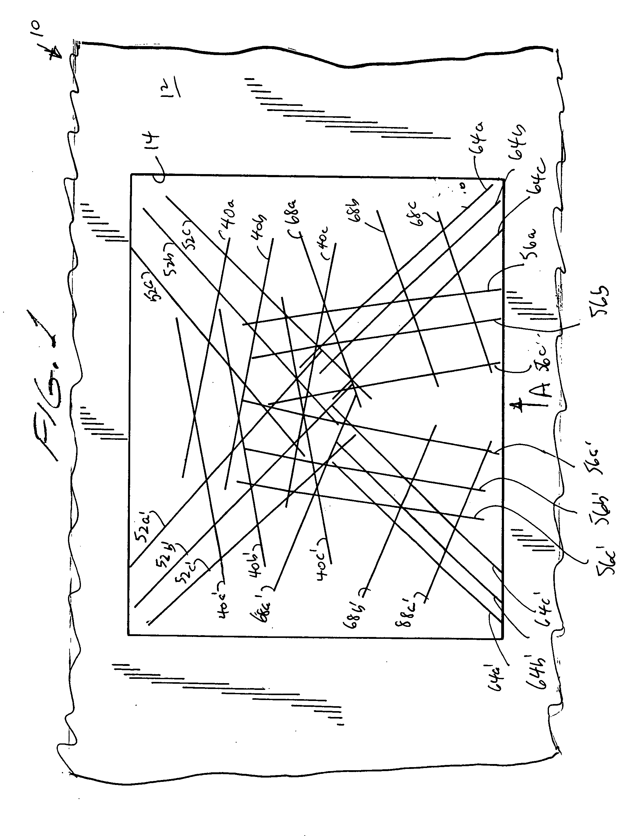
[0021] As described in detail below, a scan pattern generator underneath the window within the counter generates a scan pattern at the window 14, and projects the scan pattern into space upwardly away from the window. The scan pattern is comprised of multiple scan lines as shown in FIG. 1. At least one of the scan lines is intended to sweep ove...


PUM


Abstract

Scan lines are projected through a single horizontal window of a slot scanner and onto multiple surfaces of a product bearing a bar code symbol to be electro-optically read. The symbol may be in any orientation and on any vertical surface of the product, as well as on the bottom surface of the product.

Description

BACKGROUND OF THE INVENTION [0001] 1. Field of the Invention [0002] The present invention generally relates to a flat bed reader for electro-optically reading indicia associated with objects passing through the reader and, more particularly, to generating a scan pattern over multiple surfaces of each object to insure reliable reading of the associated indicia. [0003] 2. Description of the Related Art [0004] Flat bed laser readers, also known as horizontal slot scanners, have been used to electro-optically read bar code symbols, particularly of the Universal Product Code (UPC) type, at a point-of-transaction workstation in supermarkets, warehouse clubs, department stores, and other kinds of retailers for many years. As exemplified by U.S. Pat. Nos. 5,059,779; 5,124,539 and 5,200,599, a single, horizontal window is set flush with, and built into, a horizontal countertop of the workstation. Products to be purchased bear an identifying symbol and are slid across the horizontal window th...

Claims


Application Information

Patent Timeline
Patent Type & Authority Applications(United States)
IPC IPC(8): G02B26/10G02B26/12G06K7/10
CPCG06K7/10693G06K7/10623G06K7/10G06K7/10554
Inventor BARKAN, EDWARDSHEPARD, HOWARD
Owner SYMBOL TECH INC
Why Eureka
Try Eureka