Speaker device and mobile phone

a technology of speaker device and mobile phone, which is applied in the direction of transducer diaphragm, transducer details, instruments, etc., can solve the problem that the speaker device is not applied, and achieve the effects of low frequency sound, high efficiency and high sensitivity

Inactive Publication Date: 2007-06-28
PIONEER CORP +1
View PDF8 Cites 171 Cited by
  • Summary
  • Abstract
  • Description
  • Claims
  • Application Information

AI Technical Summary

Benefits of technology

[0010] The present invention has been achieved in order to solve the above problem. It is an object of this invention to provide a speaker device capable of obtaining high sensitivity, high efficiency and low frequency sound and able to be thin and slim.

Problems solved by technology

However, the speaker device according to the above-mentioned References-1 and 2 structurally becomes thick in the vibration direction of the diaphragm, and there is such a problem that the speaker device is hardly applied to a recent mobile phone of a thin-type.

Method used


Image

  • Speaker device and mobile phone
  • Speaker device and mobile phone
  • Speaker device and mobile phone

Examples


first embodiment

(Configuration of Speaker Device)

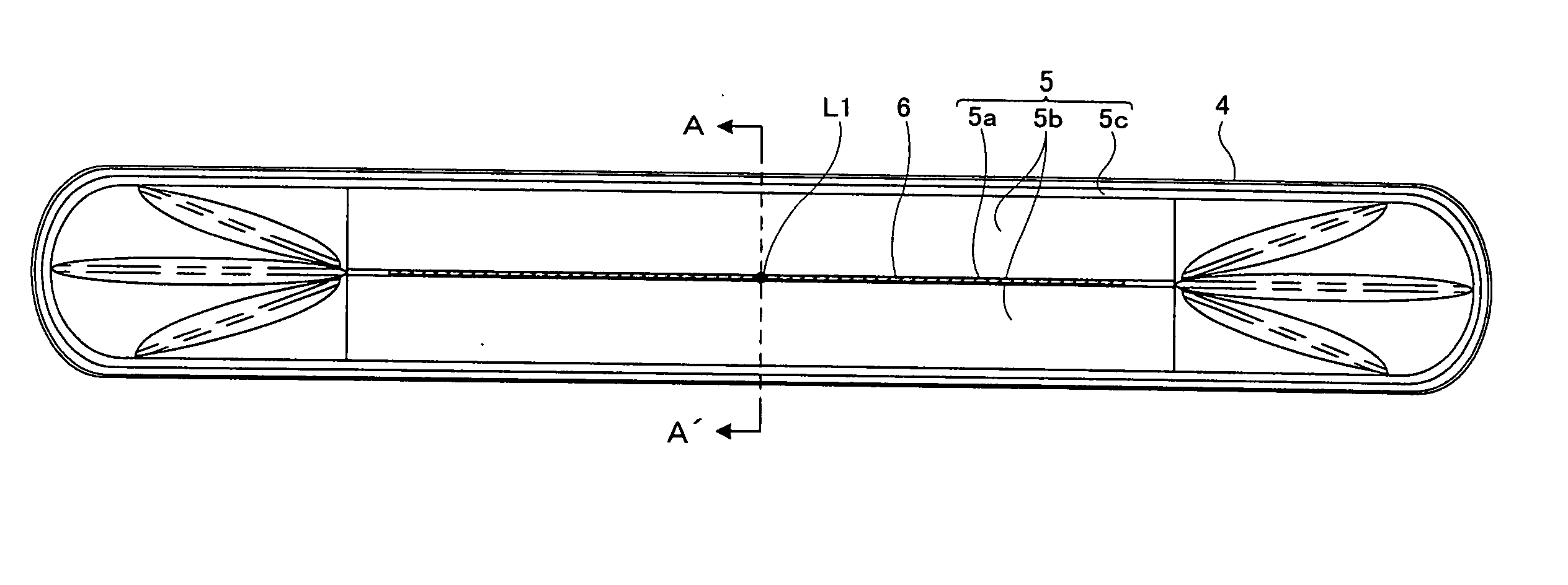
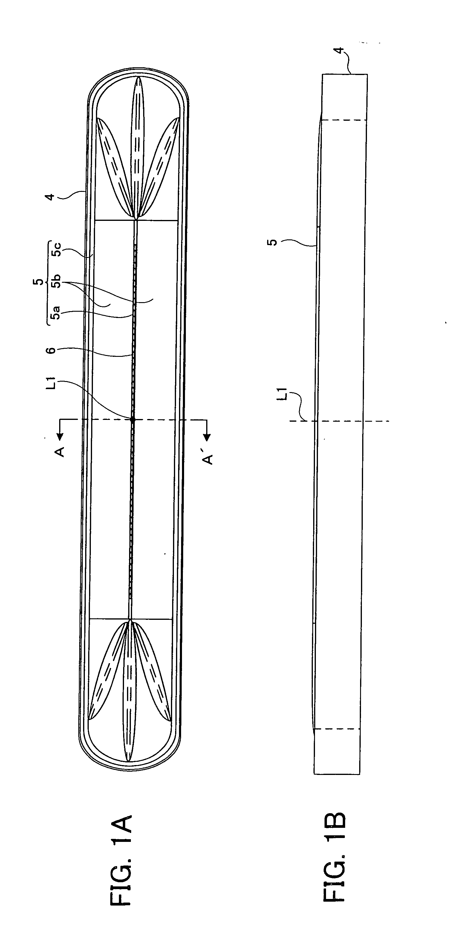
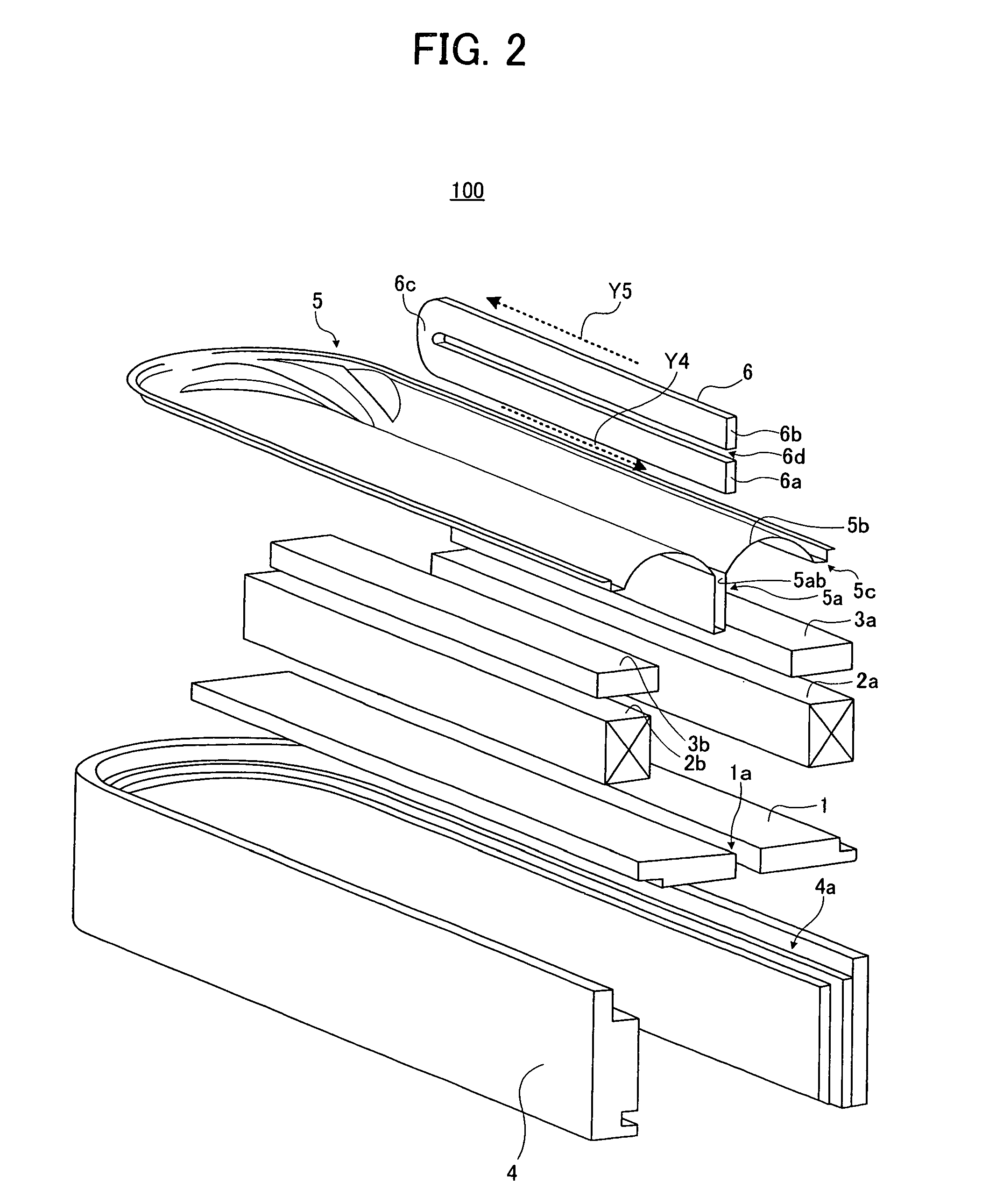
[0054]FIG. 1A shows a plane view of a speaker device 100 according to a first embodiment of the present invention when observed from a sound output direction thereof. FIG. 1B shows a side view of the speaker device 100 shown in FIG. 1A. FIG. 2 shows a disassembly perspective view corresponding to one side of the speaker device 100 taken along a cutting line A-A′ passing through its central axis L1 shown in FIG. 1A. FIG. 3 is a cross-sectional view of the speaker device 100 taken along the cutting line A-A′ shown in FIG. 1A, and it is also a cross-sectional view thereof when cut by a plane passing through the central axis L1. Hereinafter, a description will be given of the configuration of the speaker device 100 according to the first embodiment of the present invention.

[0055] The speaker device 100 mainly includes an internal-magnet-type magnetic circuit 30 having a yoke 1, a pair of magnets 2a and 2b and a pair of plates 3a and 3b, a frame 4, and...

second embodiment

[0088] Next, a description will be given of a configuration of a speaker device 200 according to a second embodiment of the present invention, with reference to FIG. 6. FIG. 6 shows a cross-sectional view of a speaker device 200 of the second embodiment when cut by a plane passing through the central axis L1. Hereinafter, the same reference numerals are given to the same components as those common with the first embodiment, and explanations thereof are simplified or omitted.

[0089] When the second embodiment is compared with the first embodiment, their configurations are substantially common. However, the entire first parallel part 6a and the entire second parallel part 6b arranged above it, being the components of the voice coil 6, are arranged in the recessed part 5a of the diaphragm 5 in the first embodiment, but the entire first parallel part 6a and the part of the second parallel part 6b arranged above it, being the components of the voice coil 6, are arranged in the recessed p...

third embodiment

[0090] Next, a description will be given of a configuration of a speaker device 300 according to a third embodiment of the present invention, with reference to FIG. 7. FIG. 7 shows a cross-sectional view of the speaker device 300 according to the third embodiment when cut by a plane passing through the central axis L1. Hereinafter, the same reference numerals are given to the components common with those of the first embodiment, and explanations thereof are simplified or omitted.

[0091] When the third embodiment and the first embodiment are compared, their configurations are substantially common. However, they are different in the number of magnets 2 and plates 3.

[0092] Concretely, the speaker device 300 according to the third embodiment includes the magnet 2a and the plate 3a, but it does not include the magnet 2b and the plate 3b. Instead, in the third embodiment, the speaker device 300 includes a magnetic body 8 at the position corresponding to the magnet 2b and the plate 3b. In...


PUM


Abstract

A speaker device includes: a magnetic circuit which includes two magnetic gaps; a diaphragm which is arranged at a position passing through at least the two magnetic gaps and includes a recessed part extending in a direction substantially orthogonal with respect to an extending direction of a magnetic flux in the magnetic gaps; and a voice coil, formed into an annular shape, which includes a first parallel part extending in one direction and a second parallel part extending in a direction in parallel with the first parallel part and opposite to the first parallel part with a constant space. Particularly, the first parallel part and the second parallel part are arranged in a direction in parallel with an extending direction of the recessed part, respectively, and the first parallel part and the second parallel part are arranged in the recessed part to be positioned in the two magnetic gaps, respectively.

Description

BACKGROUND OF THE INVENTION [0001] 1. Field of the Invention [0002] The present invention relates to a configuration of a speaker device preferably usable for a mobile phone. [0003] 2. Description of Related Art [0004] Conventionally, there is known a Ryffel-type speaker including a rectangular diaphragm and a liner voice coil arranged at a central part of the diaphragm (see “New Edition Encyclopedia of Speakers and enclosures” Tamon Saeki, Seibundo-Shinkosha, Aug. 1, 2002, Vol. 3, P. 40, for example). The speaker having a configuration of this kind is disclosed in Japanese Patent Applications Laid-open under No. 11-187484 and No. 10-191494, which are referred to as References-1 and 2, respectively. [0005] The speaker according to Reference-1 mainly includes two diaphragms and a magnetic circuit including two, i.e., upper and lower magnetic gaps in parallel with each other and having opposite magnetic flux directions. At substantial centers on rear surfaces of the respective diaphra...

Claims


Application Information

Patent Timeline
Patent Type & Authority Applications(United States)
IPC IPC(8): H04R9/06
CPCH04R9/025H04R9/06H04R2499/11
Inventor MITOBE, KUNIOFURUTO, AKIHIKO
Owner PIONEER CORP
Why Eureka
Try Eureka