
Structure for tripod constant velocity joint and method of assembling roller assembly

a constant velocity joint and structure technology, applied in the direction of yielding couplings, rotary machine parts, couplings, etc., can solve the problems of horizontal vibration of vehicles and axial force, and achieve the effects of reducing the generation of axial force, minimizing frictional force, and maintaining structural stability of the constant velocity join

Inactive Publication Date: 2007-06-28
KOREA FLANGE
View PDF6 Cites 15 Cited by
  • Summary
  • Abstract
  • Description
  • Claims
  • Application Information

AI Technical Summary

Benefits of technology

[0005]Accordingly, the present invention has been made keeping in mind the above problem occurring in the prior art, and an object of the present invention is to provide a structure for a tripod constant velocity joint and a method of assembling a roller assembly, which maintain the structural stability of the tripod constant velocity joint, and minimize the frictional force between an outer roller and a track and the frictional force between a trunnion and an inner roller, using a roller groove formed on the outer roller and a plurality of recesses formed on the trunnion, thus remarkably reducing the generation of an axial force, therefore securing the stable operation and durability of the constant velocity joint.

Problems solved by technology

Further, the axial force is problematic in that it causes horizontal vibration of the vehicle.

Method used


Image

  • Structure for tripod constant velocity joint and method of assembling roller assembly
  • Structure for tripod constant velocity joint and method of assembling roller assembly
  • Structure for tripod constant velocity joint and method of assembling roller assembly

Examples


Embodiment Construction

[0023]Hereinafter, the preferred embodiment of the present invention will be described in detail with reference to the accompanying drawings.

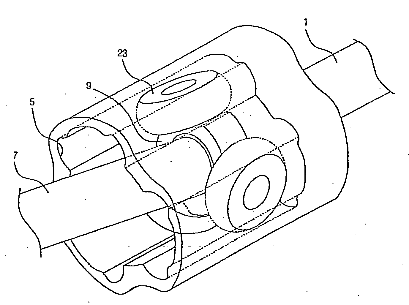
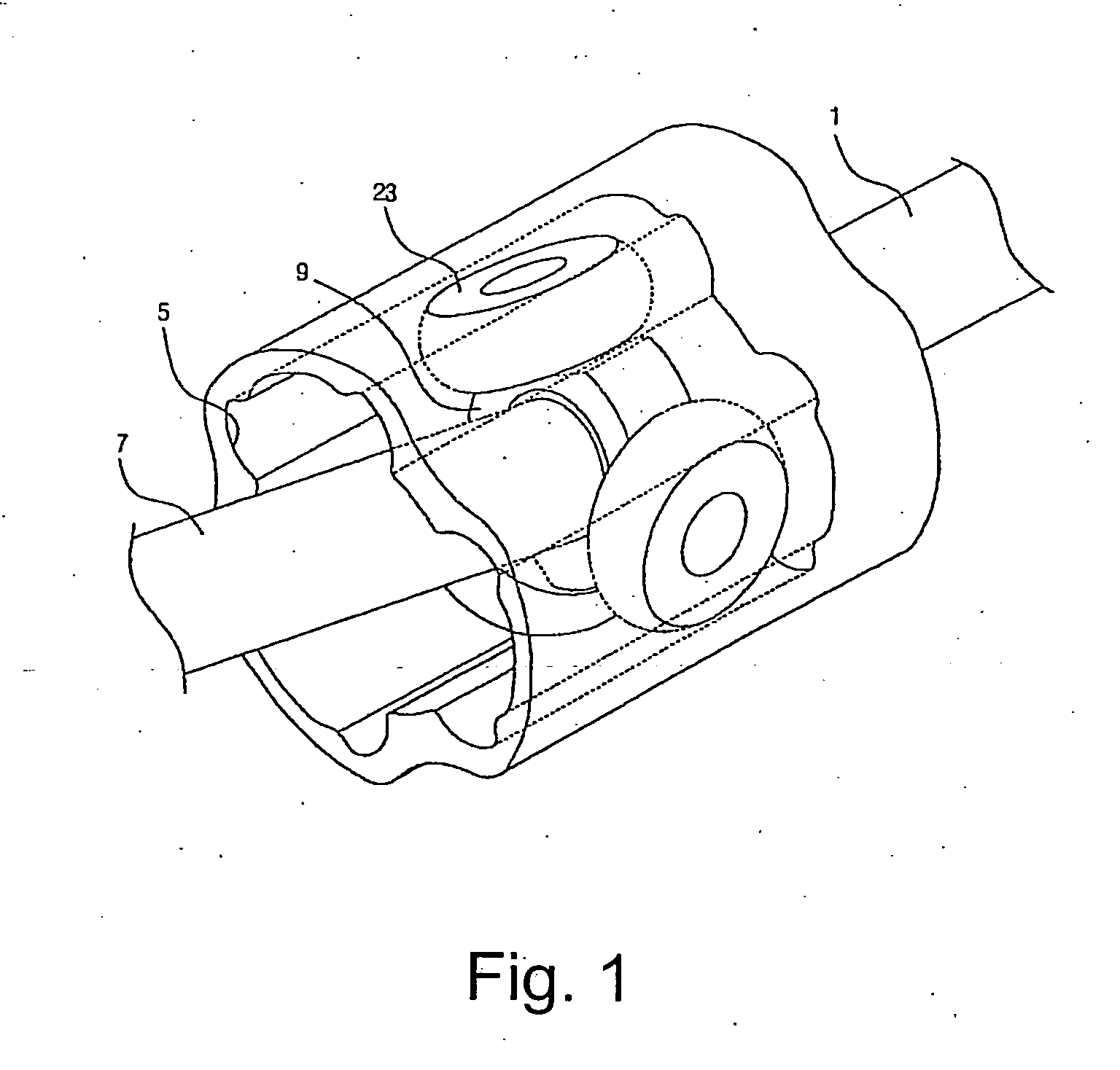
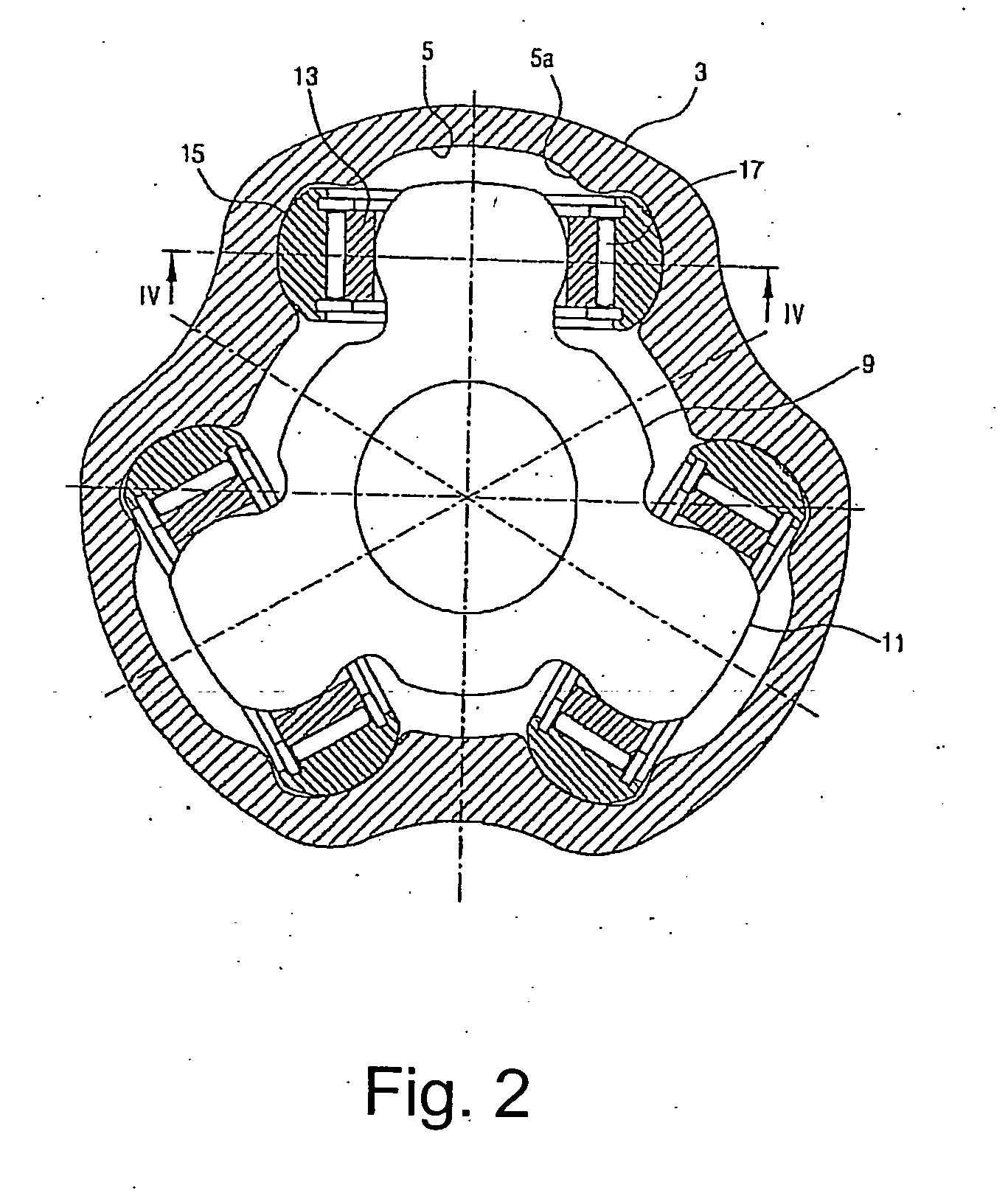
[0024]FIG. 1 is a perspective view showing a structure for a tripod constant velocity joint, according to the present invention, FIG. 2 is a sectional view showing a housing and a spider of FIG. 1, in an assembled state, FIG. 3 is an enlarged view showing a part of FIG. 2, FIG. 4 is a sectional view taken along line IV-IV of FIG. 2, FIG. 5a is a plan view showing an inner roller, according to the present invention, FIG. 5b is a sectional view taken along line Z-Z of FIG. 5a, FIG. 5c is an enlarged sectional view showing portion F of FIG. 5b, FIG. 5d is a sectional view taken along line V-V of FIG. 5a, FIG. 6 is a view showing a structure of a trunnion, according to the present invention, FIG. 7 is a sectional view taken along line VI-VI of FIG. 6, FIG. 8 is a sectional view taken along line VII-VII of FIG. 6, FIG. 9 is a sectional view taken al...


PUM


Abstract

Disclosed herein are a structure for a tripod constant velocity joint and a method of assembling a roller assembly, which maintain the structural stability of the tripod constant velocity joint, and minimize the frictional force between a trunnion and a track, thus remarkably reducing the generation of axial force, therefore ensuring the stable operation and durability of the constant velocity joint. The structure for the tripod constant velocity joint includes an inner roller and an outer roller provided between a track of a housing and a trunnion of a spider. A roller groove is formed on a central portion of an outer surface of the outer roller in a circumferential direction of the outer roller. Further, a plurality of recesses is formed on a surface of the trunnion to reduce a contact area with the inner roller.

Description

BACKGROUND OF THE INVENTION[0001]1. Field of the Invention[0002]The present invention relates generally to a structure for a tripod constant velocity joint and a method of assembling a roller assembly and, more particularly, to a structure for a tripod constant velocity joint and a method of assembling a roller assembly, which maintain the structural stability of the tripod constant velocity joint, and minimize the frictional force between a trunnion and a track, thus remarkably reducing the generation of axial force, therefore ensuring the stable operation and durability of the constant velocity joint.[0003]2. Description of the Related Art[0004]Generally, a tripod constant joint is constructed to transmit power, using a housing, which is integrally coupled to a stub shaft, and a spider, which is inserted into the housing and spline-coupled to a half shaft. Three trunnions are provided on the spider. Each of the trunnions is provided with rollers and bearings so as to absorb relati...

Claims


Application Information

Patent Timeline
Patent Type & Authority Applications(United States)
IPC IPC(8): F16D3/26
CPCF16D3/2055F16D2003/2026Y10S464/905F16D3/202F16D3/20
Inventor YOON, DONG YOUNG
Owner KOREA FLANGE
Learn More