Method and apparatus for removing material from an intervertebral disc space, such as in performing a nucleotomy

a technology of intervertebral discs and material removal, which is applied in the field of removal of intervertebral disc material, can solve the problems of intervertebral discs being overtly stressed by excessive movement, damaged or displaced,

Active Publication Date: 2007-06-28
MEDTRONIC XOMED INC
View PDF17 Cites 90 Cited by
  • Summary
  • Abstract
  • Description
  • Claims
  • Application Information

AI Technical Summary

Problems solved by technology

Intervertebral discs are elastic in nature, and can be damaged or displaced.
For example, intervertebral discs can be overtly stressed by excessive movement, excess body weight, injury, disease, and/or gradual deterioration with age.
Intervertebral disc injuries or other abnormalities can result in serious back pain and physical disability, and are often chronic and difficult to treat.
Similarly, the disc may degenerate over time, leading to a collapse of the disc space.
While viable, use of manual instrumentation can render the procedure overly time consuming.
This increases the chance of damage to sensitive structures adjacent to the spine (vascular and

Method used


Image

  • Method and apparatus for removing material from an intervertebral disc space, such as in performing a nucleotomy
  • Method and apparatus for removing material from an intervertebral disc space, such as in performing a nucleotomy
  • Method and apparatus for removing material from an intervertebral disc space, such as in performing a nucleotomy

Examples


Embodiment Construction

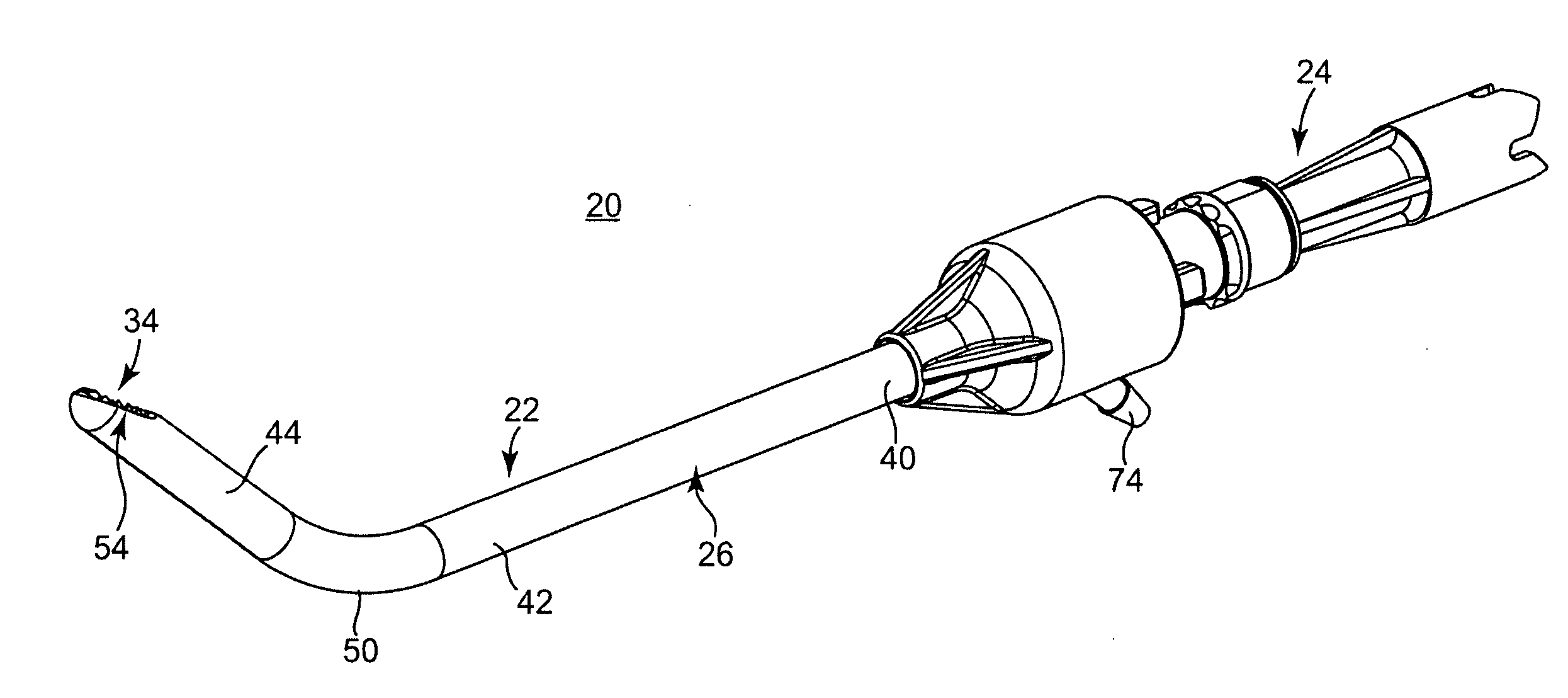
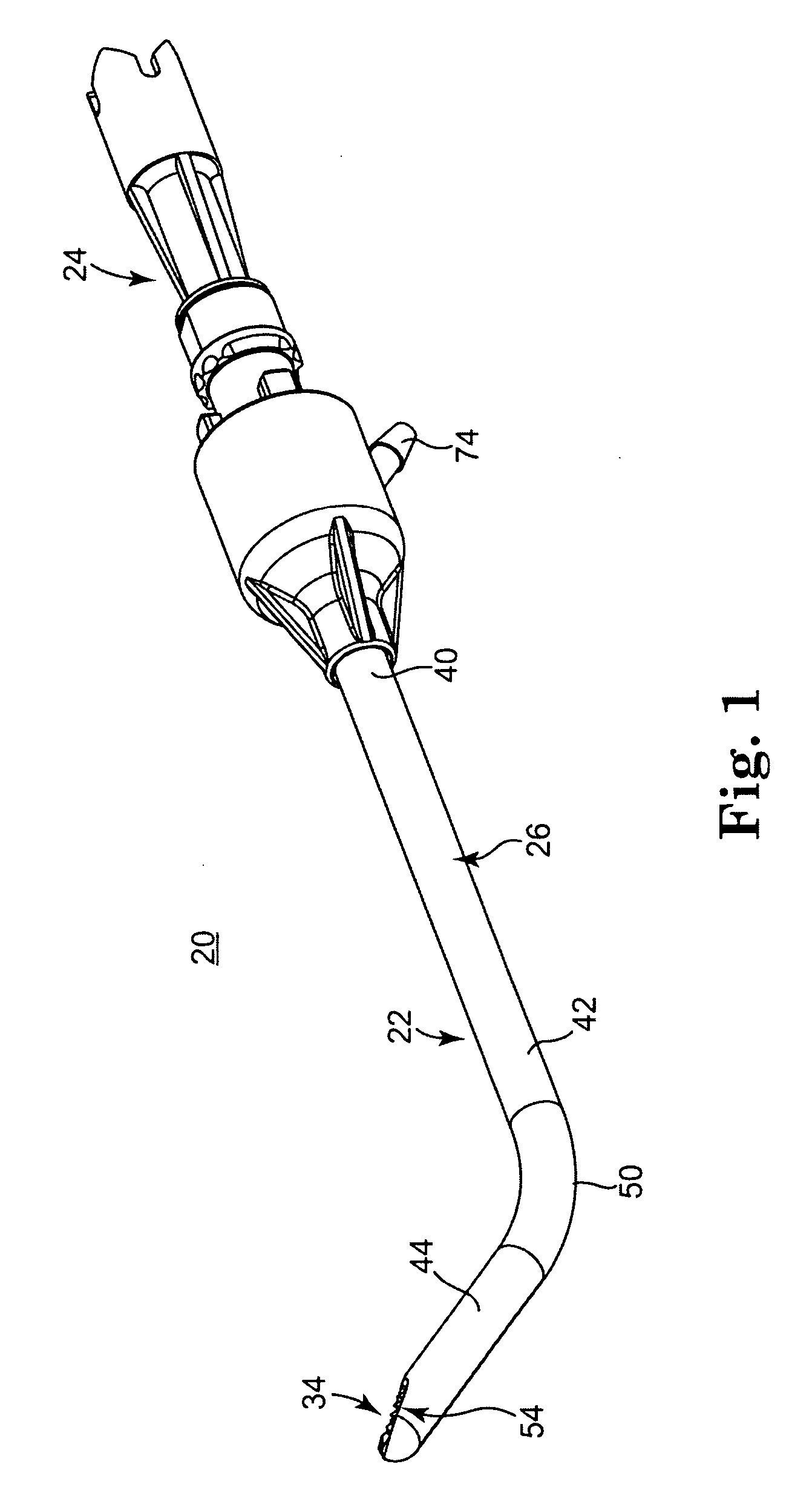
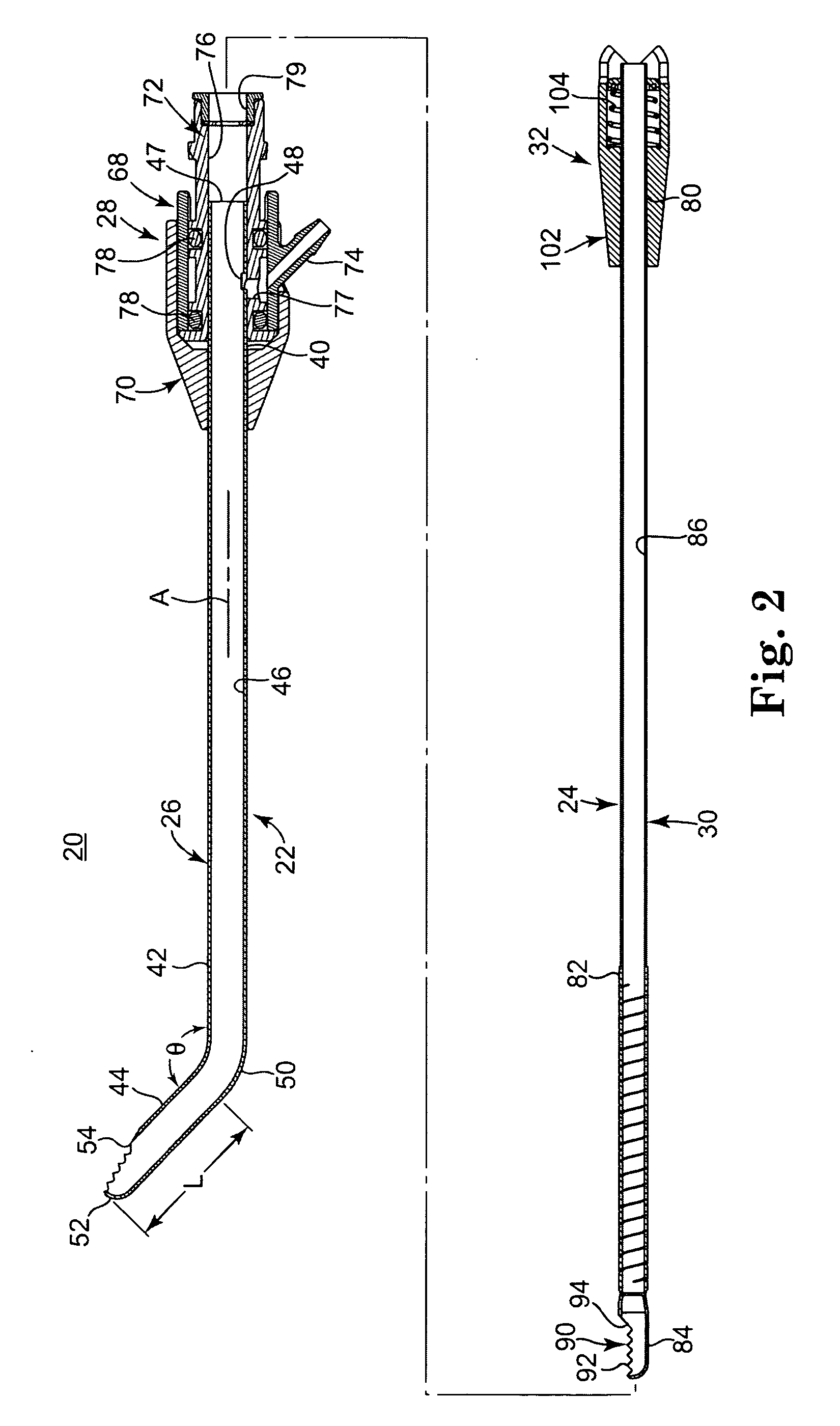
[0019] One embodiment of an intervertebral disc shaving instrument 20 in accordance with the principles of the present invention is shown in FIGS. 1 and 2. The instrument 20 includes an outer tubular assembly 22 and an inner tubular assembly 24. The outer tubular assembly 22 includes an outer tubular member 26 and a first hub assembly 28. Similarly, the inner tubular assembly 24 includes an inner tubular member 30 (best seen in FIG. 2) and a second hub assembly 32. Details on the various components are provided below. In general terms, however, the inner tubular member 30 is coaxially disposed within the outer tubular member 26, with the tubular members 26, 30 combining to define a bodily material shaving head 34 (FIG. 1). During use, the instrument 20 is coupled to a powered handpiece (not shown) that rotates the second hub assembly 32, and thus the inner tubular member 30, relative to the outer tubular member 26 in an oscillating fashion, to effectuate shearing of intervertebral d...


PUM


Abstract

Instrument and method for removing material from an intervertebral disc. The instrument includes outer and inner tubular members. The outer tubular member defines a passage and a cutting window. The inner tubular member is coaxially disposed within the passage, and defines a central lumen and a cutting tip. The cutting tip forms an open mouth having a plurality of teeth. Upon assembly, the cutting tip is exposed within the cutting window combining to define a shaving head. A powered handpiece is coupled to the inner tubular member, and the shaving head is inserted into an intervertebral disc and positioned such that the cutting tip contacts targeted material (e.g., nucleus, annulus and/or end plate). The handpiece is activated to rotate the cutting tip relative to the cutting window. Contacted material is sheared between an edge of the cutting window and the teeth of the cutting tip.

Description

BACKGROUND OF THE INVENTION [0001] The present invention relates to removal of intervertebral disc material. More particularly, it relates to a method and powered device for removing some or all of the material (tissue, cartilaginous bone, etc.) associated with an intervertebral disc, for example in performing a nucleotomy. [0002] The vertebral spine includes, amongst other structures, a series of bony vertebrae, adjacent ones of which are supported and separated by an intervertebral disc. In a healthy spine, the discs maintain separation between the vertebrae, promoting fluid circulation throughout the spine, and providing a cushioning effect between the vertebral structures. An intervertebral disc generally includes an annulus fibrosis (or “annulus”), a nucleus pulposus (or “nucleus”), and opposing end plates. The end plates are akin to cartilaginous bone and serve to attach adjacent vertebrae to the disc. The nucleus is disposed between the end plates, circumferentially constrain...

Claims


Application Information

Patent Timeline
IPC IPC(8): A61B17/00
CPCA61B17/32002A61B2017/00261A61B2017/2904
Inventor OLIVER, DANA A.ADAMS, KENNETH M.FRANCIS, TOM J.
Owner MEDTRONIC XOMED INC
Why Eureka
Try Eureka