Improvements to silicon nuclear implants

A nuclear implant, implant technology, applied in spinal implants, medical science, prosthesis, etc., can solve the problem of not connecting or attaching

Inactive Publication Date: 2014-07-09
CLARIANCE SAS
View PDF7 Cites 0 Cited by
  • Summary
  • Abstract
  • Description
  • Claims
  • Application Information

AI Technical Summary

Problems solved by technology

[0007] It should be pointed out that this type of implant has the following problem: Since the implant is not connected or attached to the corresponding verteb

Method used


Image

  • Improvements to silicon nuclear implants
  • Improvements to silicon nuclear implants
  • Improvements to silicon nuclear implants

Examples


Embodiment Construction

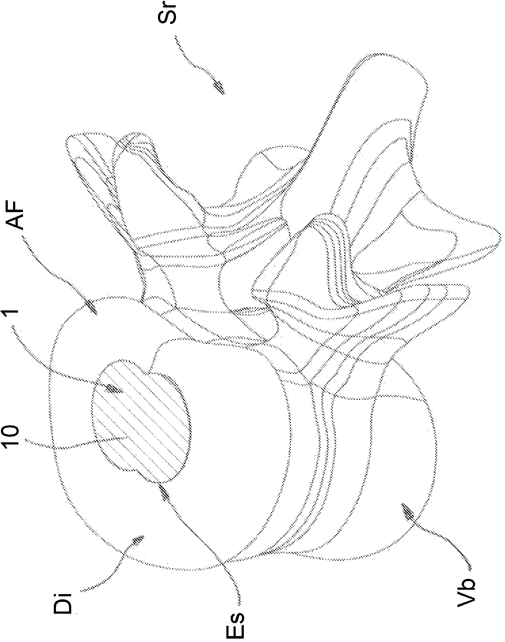
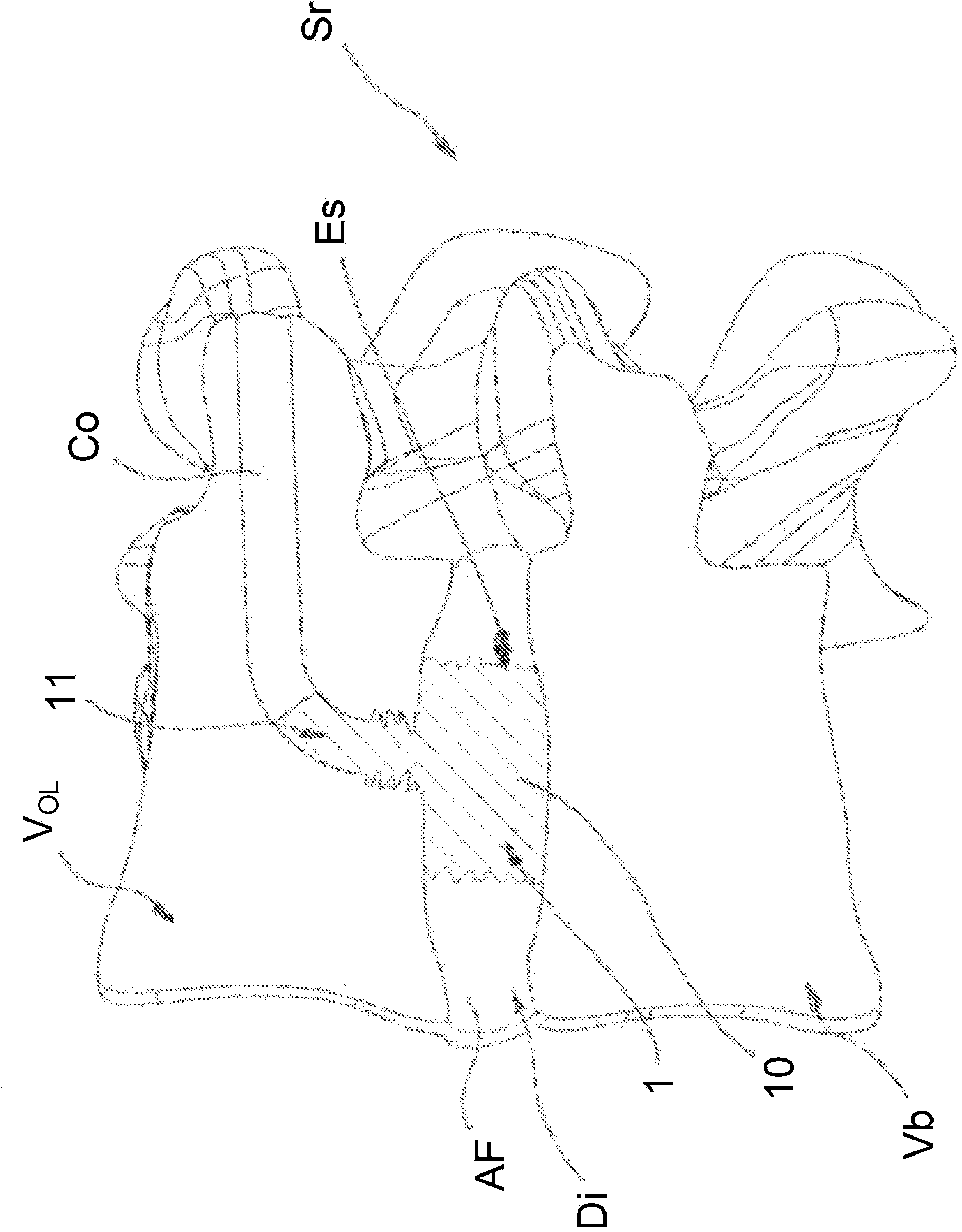
[0019] figure 1 and 2 A vertebral segment Sr of the spine is shown, at least one of its superior vertebra Va and inferior vertebra Vb will be pierced using a drilling device (not shown), giving at least one bone tunnel with an arcuate profile Co to reach the lesion The upper surface of the middle disc bottom.

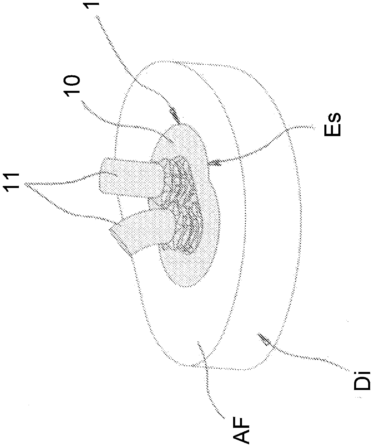
[0020] For example, drilling the upper vertebra Va with a curved profile enables the use of bone and percutaneous surgical methods to reach the nucleus of the intermediate disc Di, and then the necessary operations can be performed on the damaged intermediate disc until The nucleus pulposus space Es is obtained at the center of the "fibrous annulus" AF.

[0021] Drilling of the upper vertebra Va and / or the lower vertebra Vb having an arcuate profile can be performed, for example, using a drilling device described and protected in patent application FR11 / 00199 belonging to the applicant.

[0022] When a bone canal Co with a curved shape is obtained, an injection devic...


PUM


Abstract

The nuclear implant according to the present invention consists of a nucleus (10) arranged inside a nuclear space (Es) obtained after nucleotomy of the intervertebral disc (Di) and at least one extension (11) penetrating inside at least one channel (Co) formed in the vertebral body of the corresponding vertebra (Va, Vb) to strengthen and provide a link between the nuclear implant (1) and the bone body of the vertebra (Va) and/or (Vb), by diffusion or migration of the viscoelastic material forming said nuclear implant into the cancellous bone of said vertebra.

Description

technical field [0001] The present invention relates to a silicone core implant, arranged between the upper and lower vertebra of a vertebral segment, constituting an intermediate spinal support that absorbs shocks and ensures mobility of the functional unit formed by said vertebrae. Background technique [0002] Degeneration of the nucleus is usually the first factor leading to degeneration of the intervertebral disc and thus the interface. This degeneration can cause a hernia, and the problem is usually treated with nuclear diagnostic therapy. [0003] However, although the pain disappeared immediately postoperatively, the loss of disc height and excessive motion of successive segments gradually exacerbated segmental degeneration, pain reappeared and sometimes resulted in degeneration of adjacent vertebral levels. [0004] Early nuclear replacement in such patients may be an effective alternative to total disc replacement or fusion of spinal segments. [0005] In fact, m...

Claims


Application Information

Patent Timeline
IPC IPC(8): A61F2/44
CPCA61F2/442A61B2017/00261A61F2/441A61F2002/30065A61F2002/30069A61F2002/30548A61F2002/30563A61F2002/30581A61F2002/30583A61F2002/30878A61F2002/444
Inventor A·托尼尔G·维亚尔特J·Y·勒罗伊A·比尔隆
Owner CLARIANCE SAS
Why Eureka
Try Eureka