Suture anchor with insert-molded suture eyelet

a suture anchor and eyelet technology, applied in the field of sutures, can solve the problems of reducing integrity, mechanically weakening the drive head, premature suture detachment, etc., and achieve the effect of increasing the viability of the suture eyel

Active Publication Date: 2007-06-28
ARTHREX
View PDF10 Cites 72 Cited by
  • Summary
  • Abstract
  • Description
  • Claims
  • Application Information

AI Technical Summary

Benefits of technology

[0009] The suture anchor of the present invention overcomes disadvantages of the prior art, such as those noted above, by providing a loop of suture entirely insert-molded within the suture anchor. The suture loop passes around an eyelet opening developed in the drive head. The suture anchor increases suture eyelet viability during rehabilitation. The suture anchor also requires less pilot hole depth than prior devices.

Problems solved by technology

Problems arise if the structure for attaching the suture fails postoperatively and the suture detaches from the anchor prematurely.
Forming openings through the drive head of the anchor mechanically weakens the drive head.
These features, however, also tend to reduce integrity and weaken the drive head.

Method used


Image

  • Suture anchor with insert-molded suture eyelet
  • Suture anchor with insert-molded suture eyelet
  • Suture anchor with insert-molded suture eyelet

Examples


Embodiment Construction

[0027] In the following detailed description, reference is made to various specific embodiments in which the invention may be practiced. These embodiments are described with sufficient detail to enable those skilled in the art to practice the invention, and it is to be understood that other embodiments may be employed, and that structural and logical changes may be made without departing from the spirit or scope of the present invention.

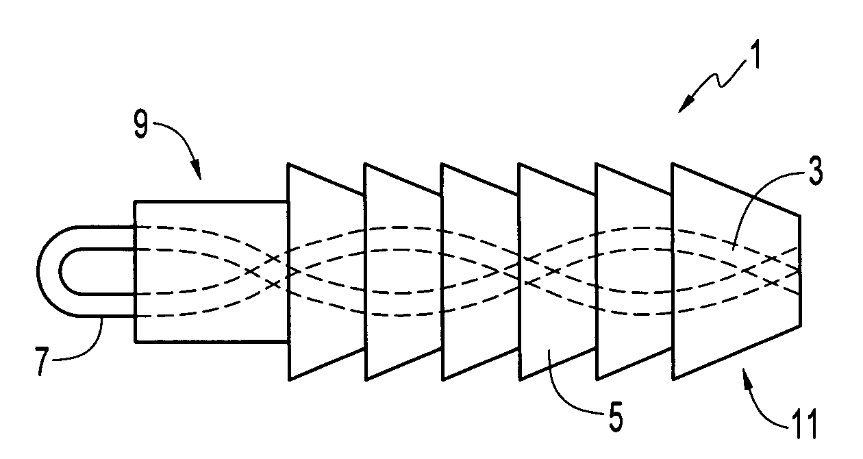
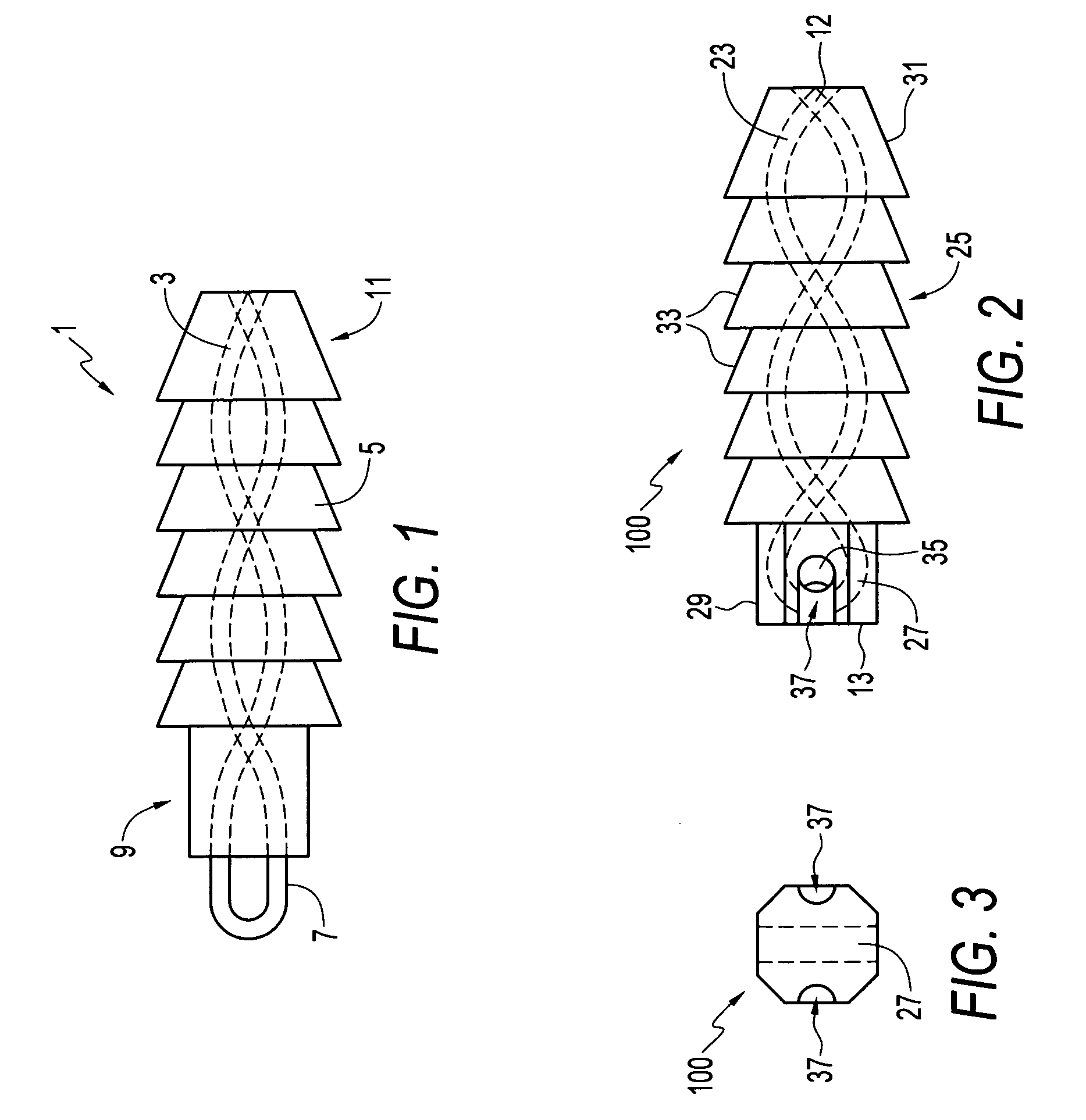
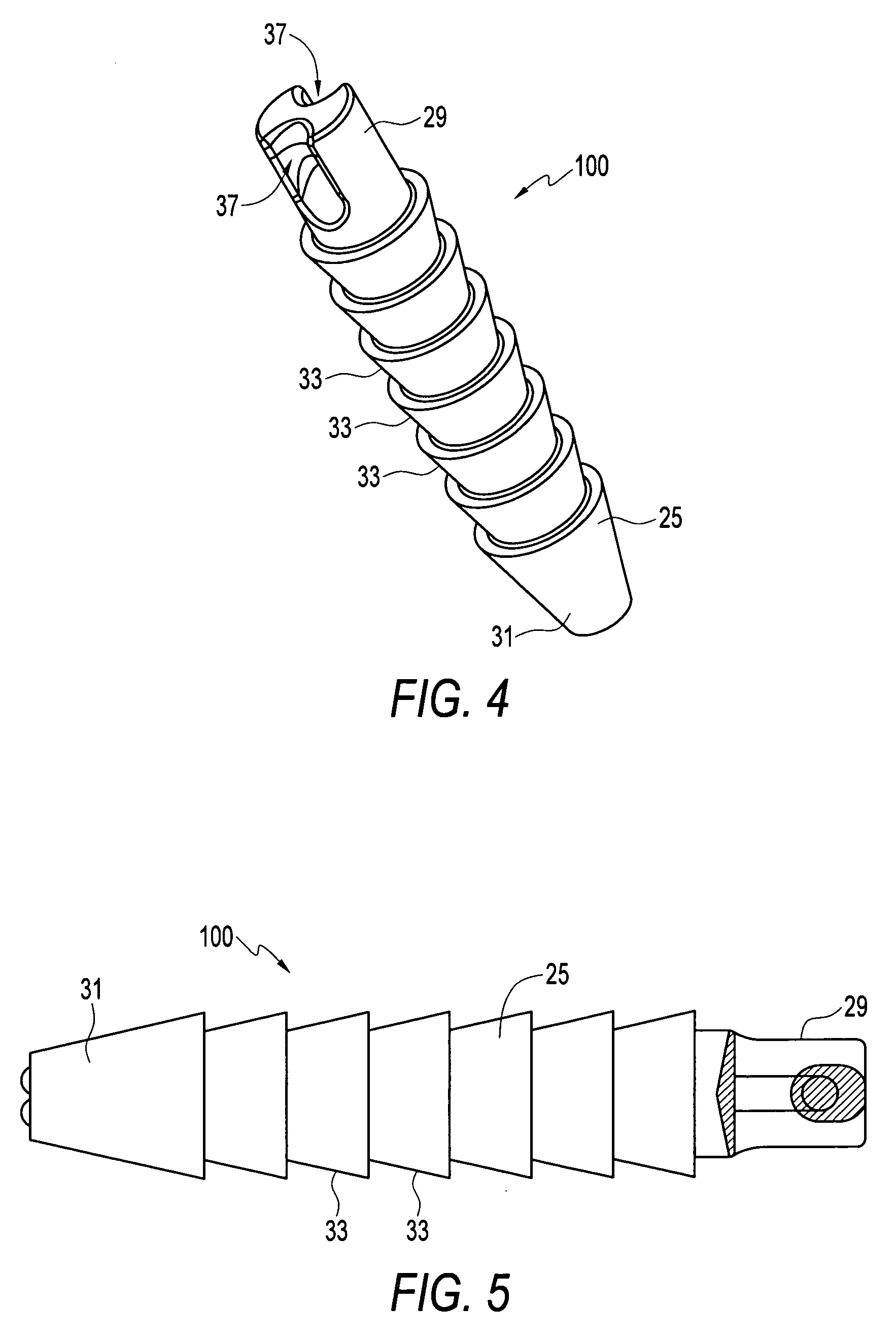
[0028] Referring now to the drawings, where like elements are designated by like reference numerals, FIGS. 2-8 illustrate a suture anchor 100 of the present invention. The suture anchor 100 includes a molded anchor body 25 having a distal end 12 and a proximal end 13. A length of strand 23 (preferably suture strand) is insert-molded completely within the suture anchor body 25. The anchor body 25 is made up of a moldable material such as a polymer plastic. An exemplary manufacturing process includes insert-molding the strand (preferably suture strand...


PUM


Abstract

An insert-molded suture anchor with a biodegradable polymer body in which a loop of suture is totally contained within the polymer. The suture anchor body features a drive end that is shaped to be received into a recess in the end of a hand driver. Anchoring ribs are formed along the remaining length of the anchor. The loop of suture which includes and eyelet for attaching a suture strand is totally embedded within the anchor body during the insert-molding fabrication process. The anchor is produced by placing the suture in an injection mold, and injecting biodegradable polymer into the mold.

Description

CROSS-REFERENCE TO RELATED APPLICATIONS [0001] This application claims the benefit of U.S. Provisional Application Ser. No. 60 / 750,061, filed Dec. 14, 2005, the disclosure of which is incorporated by reference herein in its entirety. This application is also a continuation-in-part of U.S. application Ser. No. 10 / 083,568, filed Feb. 27, 2002, which is a continuation-in-part of U.S. application Ser. No. 09 / 495,816, filed Feb. 2, 2000, now U.S. Pat. No. 6,517,564, the disclosures of which are also incorporated by reference herein in their entirety.1. FIELD OF THE INVENTION [0002] The present invention relates to apparatus and methods for surgically anchoring suture. More specifically, the present invention relates to surgically anchoring suture to bone using a suture anchor with a suture eyelet insert-molded directly within the suture anchor body. 2. DESCRIPTION OF THE RELATED ART [0003] Surgical reattachment of soft tissue to bone is a common feature of orthopedic joint repair. Surgic...

Claims


Application Information

Patent Timeline
Patent Type & Authority Applications(United States)
IPC IPC(8): A61B17/04
CPCA61B17/0401A61B2017/00526A61B2017/0409A61B2017/0414A61B2017/044A61B2017/0458A61B2017/0459
Inventor DREYFUSS, PETER J.BENAVITZ, WILLIAM C.SCHMIEDING, REINHOLD
Owner ARTHREX
Why Eureka
Try Eureka