
Implant device for osseointegration to endure weight

a technology of osseointegration and implant device, which is applied in the field of implant device for osseointegration to endure weight, can solve the problems of inability to correctly walk with the lower prosthetic leg for a long period, scratching or dermatitis, etc., and achieves the effect of increasing the contact surface area and convenient use of the lower prosthetic leg

Active Publication Date: 2007-06-28
WORKERS ACCIDENT MEDICAL CORP
View PDF1 Cites 33 Cited by
  • Summary
  • Abstract
  • Description
  • Claims
  • Application Information

AI Technical Summary

Benefits of technology

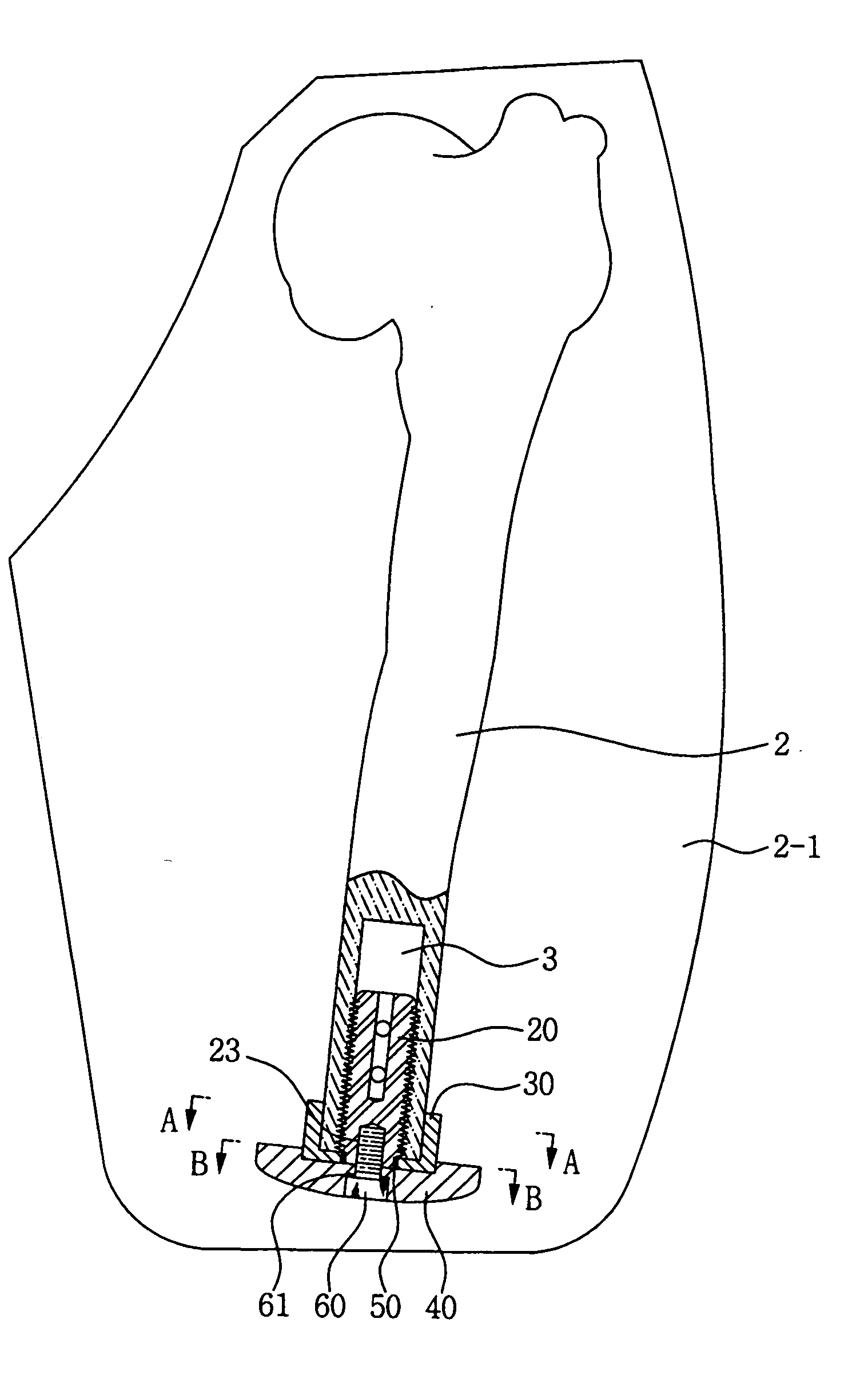
[0012] Accordingly, the present invention has been made keeping in mind the above problem in the prior art, and an object of the present invention is to provide an implant device for osseointegration to endure weight, in which an implant is inserted into the thighbone or the lower leg bone of a patient having an amputated leg and couples a weight support plate to the bone, thereby increasing the contact surface area of the implant device relative to a socket and allows the patient to conveniently use a prosthetic leg.

Problems solved by technology

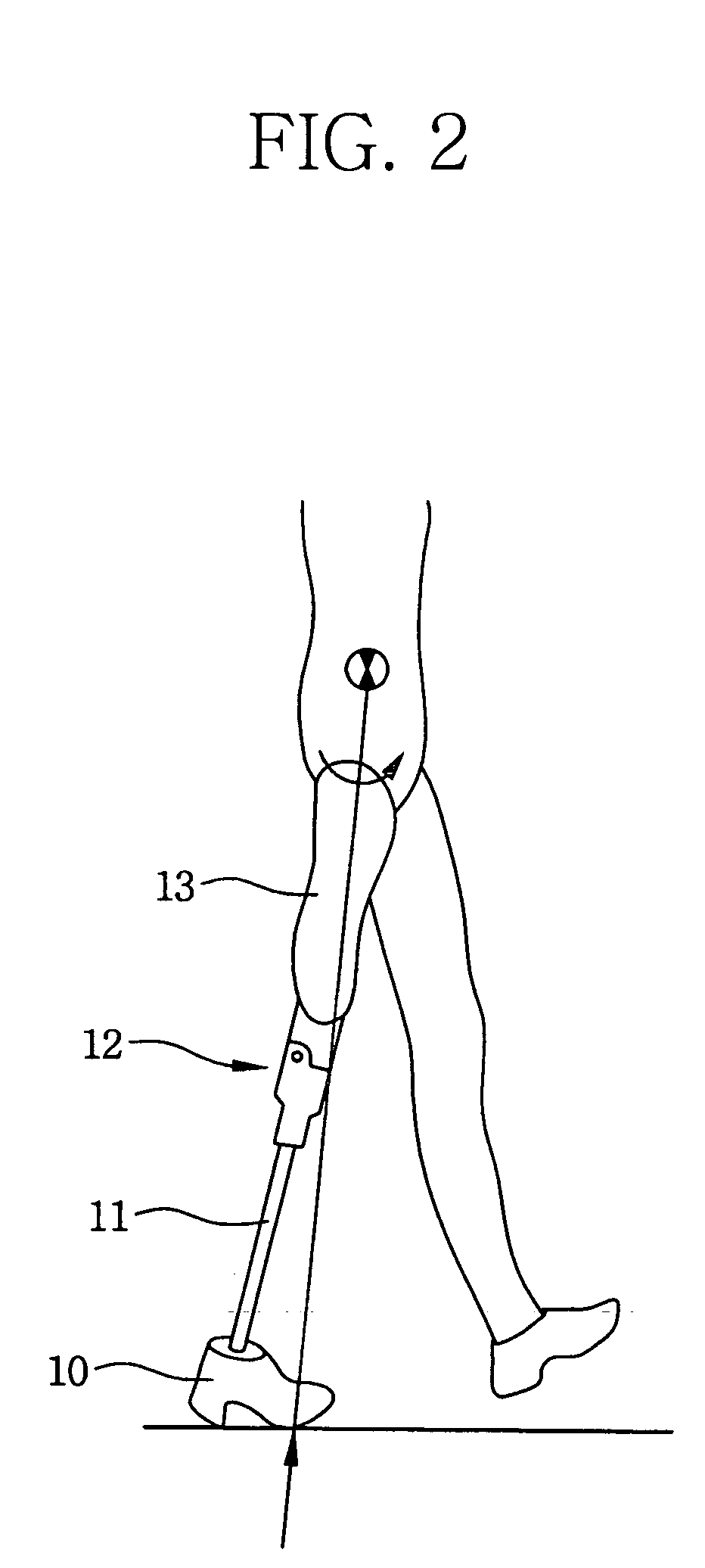
If a load is concentrically applied to both the amputated portion and the socket or the load is dispersedly applied to the entire part of the amputated portion, a scratch or dermatitis may be generated due to friction between the skin of the patient at the contact region and the socket.
Accordingly, a patient who is wearing the lower prosthetic leg for a long period cannot correctly walk because of pains.

Method used


Image

  • Implant device for osseointegration to endure weight
  • Implant device for osseointegration to endure weight
  • Implant device for osseointegration to endure weight

Examples


Embodiment Construction

[0022] Reference now should be made to the drawings, in which the same reference numerals are used throughout the different drawings to designate the same or similar components.

[0023] Herein below, a preferred embodiment of the present invention will be described in more detail with reference to the accompanying drawings.

[0024]FIG. 3 is an exploded perspective view of an implant device according to an embodiment of the present invention. FIG. 4 is a partially sectioned view showing a state that the implant device according to the present invention is inserted into the thighbone of a patient. FIG. 5 is a sectional view taken along line A-A of FIG. 4. FIG. 6 is a sectional view taken along line B-B of FIG. 4. As illustrated in the drawings, the implant device of this invention comprises an insert-type implant 20, which is tightened into an insert hole 3 that is formed vertically in a thighbone 2 or a lower leg bone 1 of a patient, both of which constitute a leg. This implant 20 has ...


PUM


Abstract

Disclosed herein is an implant device for osseointegration to endure weight. This implant device includes an insert-type implant inserted into an amputated end of a thighbone or a lower leg bone of a leg of a patient; a load dispersing adaptor having a cap shape, encompassing both the implant and the amputated end of the leg simultaneously at a lower end of the implant; a load support plate having a plate shape, coupled with the lower surface of the adaptor, whose diameter is widened, on which a plurality of muscle fixing holes are dispersedly formed; and a coupling screw, which couples the load dispersing adaptor with the insert-type implant at a bottom of the load dispersing plate through screw-coupling.

Description

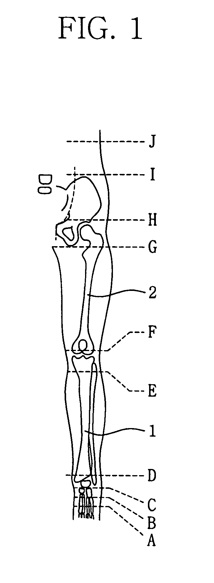
BACKGROUND OF THE INVENTION [0001] 1. Field of the Invention [0002] The present invention relates generally to implant devices for osseointegration to endure weight and, more particularly, to an implant device for osseointegration to endure weight, whereby osseointegration is possible by mounting an implant vertically into an amputated end of a thighbone or a lower leg bone, both of which constitute the leg of a patient, and by coupling both a load dispersing adapter and a load support plate to the implant, thus dispersing load to the socket of a prosthetic leg and allowing the patient to conveniently use the prosthetic leg. [0003] 2. Description of the Related Art [0004] Generally, a prosthesis is an artificial replacement to compensate for physical shortage of the legs of a patient, which is in close contact with the stump of a lost body part (among the legs), has a plurality of functions, has an external appearance closely resembling human's legs, and can be attached and used in ...

Claims


Application Information

Patent Timeline
Patent Type & Authority Applications(United States)
IPC IPC(8): A61F2/78A61F2/28
CPCA61F2/2814A61F2/30749A61F2/60A61F2002/30143A61F2002/30225A61F2002/30367A61F2002/30377A61F2002/30433A61F2002/30443A61F2002/30474A61F2002/30785A61F2002/30789A61F2002/30794A61F2002/30795A61F2002/7887A61F2220/0025A61F2220/0033A61F2220/0041A61F2230/0017A61F2230/0069A61F2002/3079
Inventor KIM, SHINMOON, MOOAHN, JAE
Owner WORKERS ACCIDENT MEDICAL CORP
Learn More