Lifting system and apparatus for constructing wind turbine towers

a technology for lifting systems and wind turbines, applied in the field of wind turbines and structural towers, can solve the problems of increasing the height of the turbine, increasing the cost of the larger and more massive towers, and increasing the cost of the equipment required to erect the wind turbine,

Inactive Publication Date: 2007-07-05
GE WIND ENERGY
View PDF99 Cites 62 Cited by
  • Summary
  • Abstract
  • Description
  • Claims
  • Application Information

AI Technical Summary

Problems solved by technology

Positioning larger turbines at greater heights comes, however, with a cost.
The cost is associated with the larger and more massive towers that are required to withstand the additional weight of the larger turbines and withstand the wind loads generated by placing structures at the greater heights where wind velocities are also greater and more sustained.
An additional cost concerns the equipment that is required to erect the wind turbine.
Towers in excess of 250,000 lbs, or higher than 100 meters, however, generally require specialized and expensive cranes to assemble the tower sections and to mount the turbine and blades on the assembled tower.
In order to amortize the expense associated with such large cranes, wind turbine farm developers desire to pack as many wind turbines as possible onto the project footprint, thereby spreading the crane costs over many wind turbines.
However, with sites having limited footprints, developers are forced to amortize transport and assembly costs of the crane using fewer turbines, which may be economically unfeasible.
Further, projects installed on rough ground require cranes to be repeatedly assembled and disassembled, which may also be economically unfeasible.
Projects located on mountain top ridges or other logistically difficult sites may, likewise, be all but eliminated due to unfeasible economics, in addition to engineering difficulties associated with locating a crane at such sites.

Method used


Image

  • Lifting system and apparatus for constructing wind turbine towers
  • Lifting system and apparatus for constructing wind turbine towers
  • Lifting system and apparatus for constructing wind turbine towers

Examples


Embodiment Construction

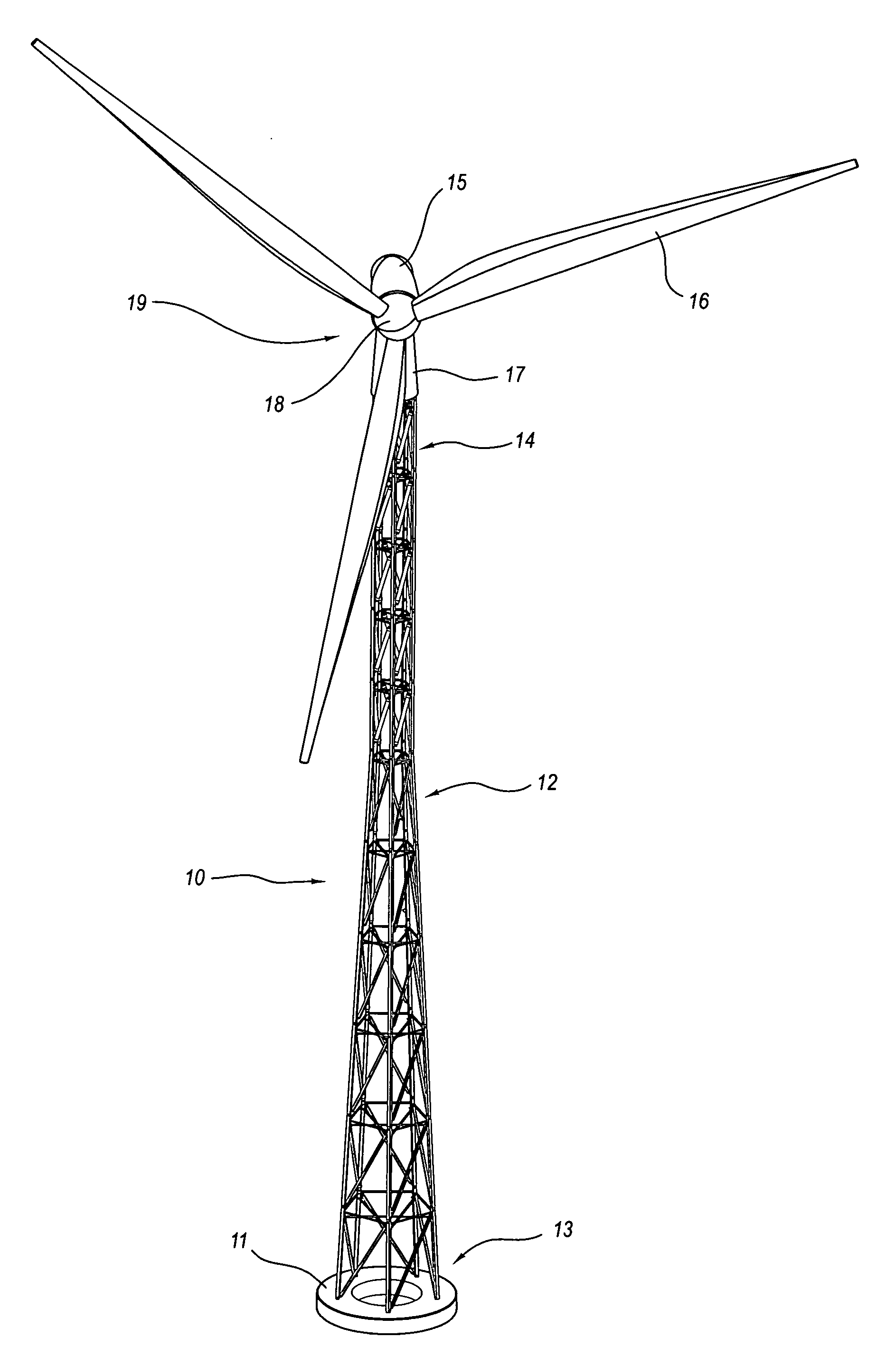
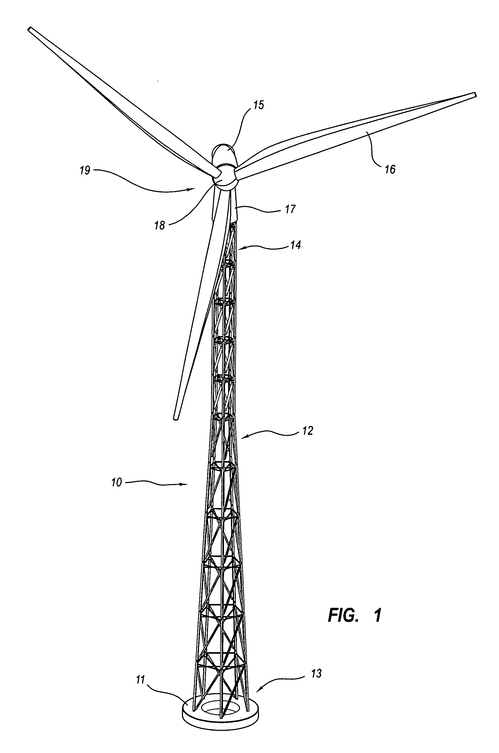
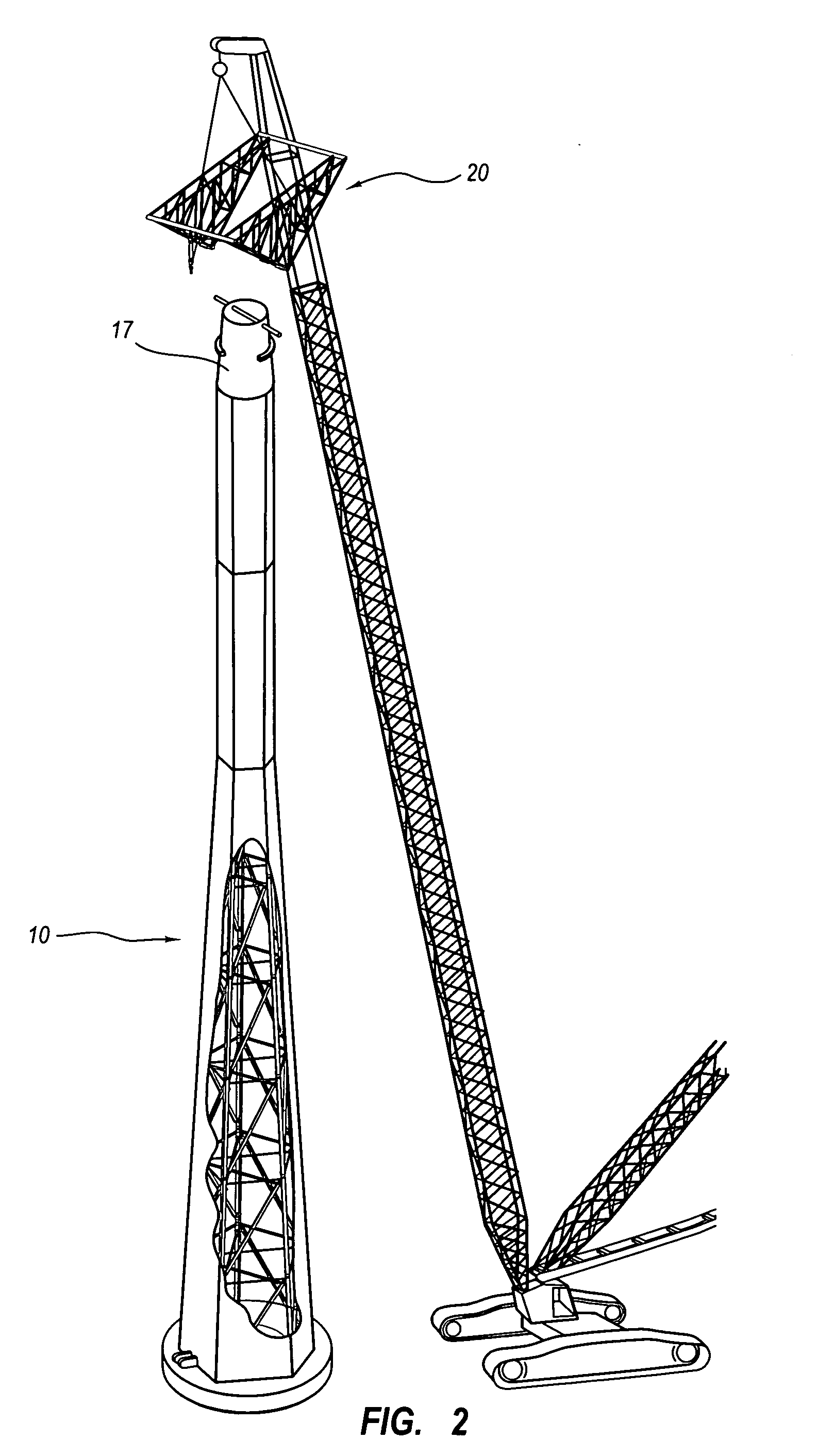
[0036] Generally, the present invention relates to apparatus and methods used to assemble or construct high elevation structural towers supporting heavy loads, as in structural towers supporting wind turbines. In further detail, the present invention relates to an apparatus and method for lifting and positioning a wind turbine and associated blades on the top of a previously constructed and assembled structural tower. In yet further detail, the present invention relates to a system and method for assembling and constructing a high elevation structural tower and for lifting and positioning a wind turbine and associated blades on the top of the previously constructed and assembled structural tower. The present invention relates in particular to wind turbine applications, where the wind turbine is elevated to heights approaching eighty to one hundred meters or higher and where rotor diameters approach seventy meters or greater. Details of exemplary embodiments of the present invention ...


PUM


Abstract

The disclosed invention is utilized for mounting a wind turbine and blade upper end of a wind turbine tower. The invention generally includes a frame or tally secured to the top bay assembly of the tower. A transverse beam is e frame or truss and extends fore of the tower when the frame or truss is in a first erally above the tower when in a second position. When in the first position, a blade assembly can be hoisted to the top of the tower. The wind turbine or blade n moved into position for mounting to the tower as the frame or truss is pivoted to n. When the turbine and blade assembly are secured to the tower, the frame or ected from the tower and lowered to the ground.

Description

RELATED APPLICATIONS [0001] This present application claims priority to U.S. Provisional Patent Application No. 60 / 755,615, entitled “Turbine and Blade Lifting Apparatus and Method,” filed Dec. 30, 2005 and U.S. Provisional Patent Application No. 60 / 848,725, entitled “Lifting System for Wind Turbine and Structural Tower,” filed Oct. 2, 2006.TECHNICAL FIELD OF THE INVENTION [0002] The present invention relates to wind turbines and structural towers and, more particularly, to equipment and methods used in assembling high elevation structural towers for wind turbines and for mounting wind turbines and blades upon high elevation structural towers. BACKGROUND OF THE INVENTION [0003] Wind turbines are an increasingly popular source of energy in the United States and Europe and in many other countries around the globe. In order to realize scale efficiencies in capturing energy from the wind, developers are erecting wind turbine farms having increasing numbers of wind turbines with larger t...

Claims


Application Information

Patent Timeline
Patent Type & Authority Applications(United States)
IPC IPC(8): E04H12/00
CPCB66C23/06B66C23/207F03D1/001Y02E10/728F05B2230/61F05B2240/9121F05B2240/916F03D11/04F03D13/20F03D13/10Y02P70/50Y02E10/72
Inventor LIVINGSTON, TRACYSCHRADER, TERRYGOLDHARDT, JAMESLOTT, JAMES
Owner GE WIND ENERGY
Why Eureka
Try Eureka