

Self-propelled vehicle for use in a conduit
- Summary
- Abstract
- Description
- Claims
- Application Information
AI Technical Summary
Benefits of technology
Problems solved by technology
Method used
Image

Examples
first embodiment
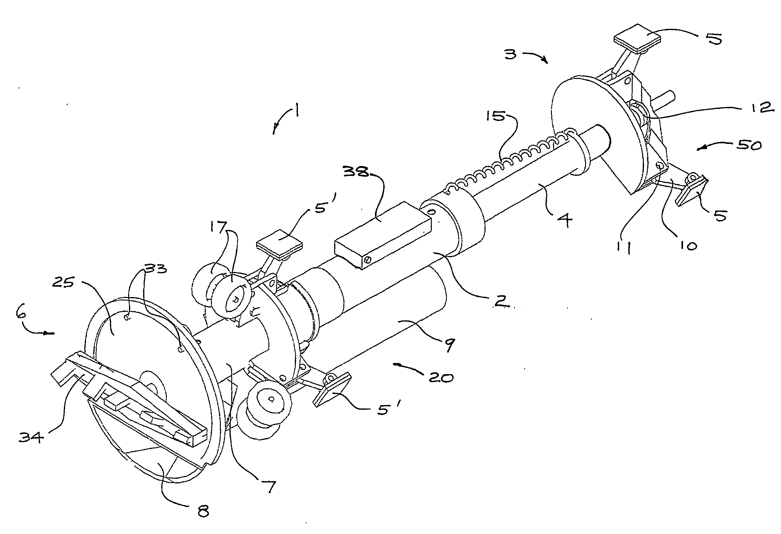
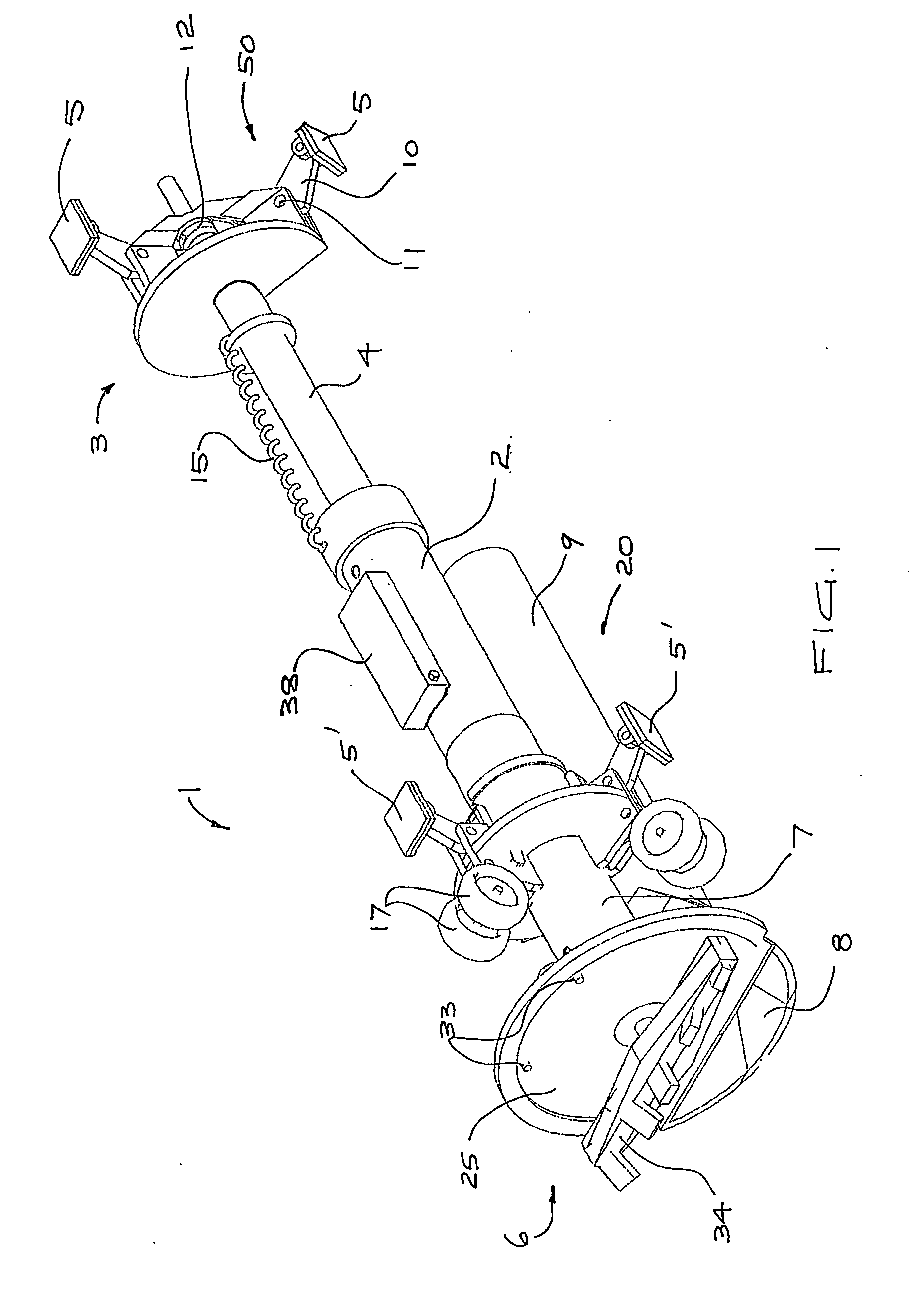
[0053]FIG. 1 illustrates the vehicle of the present invention fitted with conduit cleaning apparatus. The vehicle generally comprises a forward member 1 mounted to a hydraulic cylinder 2, and a rearward member 3 mounted to a rod 4 received in the cylinder 2. A power actuated wall-engaging mechanism (described further with reference to FIGS. 2, 3a and 3b) is provided on both the forward and rearward members 1 and 3 for extending and retracting feet 5′ and 5 respectively for selectively engaging the inner wall of a conduit 14 (see FIG. 2) to hold the members stationary. By coordinating the engagement and disengagement of the feet 5, 5′ with the movement of the forward and rearward members 1, 3 by the hydraulic cylinder 2 and rod 4, the apparatus may propel itself through the conduit 14 in either direction in a stepwise manner.
[0054] A rotary cutter 6 mounted at the front of the forward member 1 on a hydraulic motor 7 is provided for loosening material to clear or clean the conduit 14....
second embodiment
[0063] the vehicle is illustrated in FIGS. 4-8 and like numerals are used to refer to like components. The wall-engaging mechanism 50a on the rearward member 3 is also arranged generally symmetrically about the central elongate axis A of the vehicle, the feet being angularly spaced at 120°. The mechanism 50a extends and retracts the feet 5a generally radially and includes control links 66 for maintaining the wall-engaging face of each foot 5a generally parallel to the wall of the pipe. The wall-engaging mechanism 50a includes three rear legs 10a angularly spaced, each of the legs 10a being fixed between a pair of control links 66 connecting each foot 5a to the rearward member 3.
[0064] Each leg 10a is pivotally attached to the foot 5a at an outer end by a first pivot 61 and to a mount 62 fixed to the rearward member 3 by a second pivot 63. A roller 64 fixed to an inner end of the leg 10a and the three rollers 64 are received between two radially-extending flanges 69a, 69b fixed to th...
PUM
 Abstract
Description
Claims
Application Information