Tape measure utilizing mechanical decoupling of power tape extension feature for tape retraction

a technology of power extension and tape extension, which is applied in the direction of measuring devices, instruments, and mechanical means, and can solve problems such as often undesirable design

Inactive Publication Date: 2007-07-05
BLACK & DECKER INC
View PDF6 Cites 17 Cited by
  • Summary
  • Abstract
  • Description
  • Claims
  • Application Information

AI Technical Summary

Benefits of technology

[0016]FIG. 4 is a fragmentary rear elevational view, partially in section, showi...

Problems solved by technology

Although a tape measure configured with power operated tape retraction may be implemented, such a design is often undesirable due to the complexity of employing a motor that rotates under electrical power in opposed directions to accomplish tape extension and retraction.
One design issue with tape measures having only power operated tape extension is that the gearing/rollers coupled with the motor must be disengaged from the tape surface in order for the recoil spring to accomplish quick tape retraction, i.e., without having to overcome the braking force provided by the re...

Method used


Image

  • Tape measure utilizing mechanical decoupling of power tape extension feature for tape retraction
  • Tape measure utilizing mechanical decoupling of power tape extension feature for tape retraction
  • Tape measure utilizing mechanical decoupling of power tape extension feature for tape retraction

Examples


Embodiment Construction

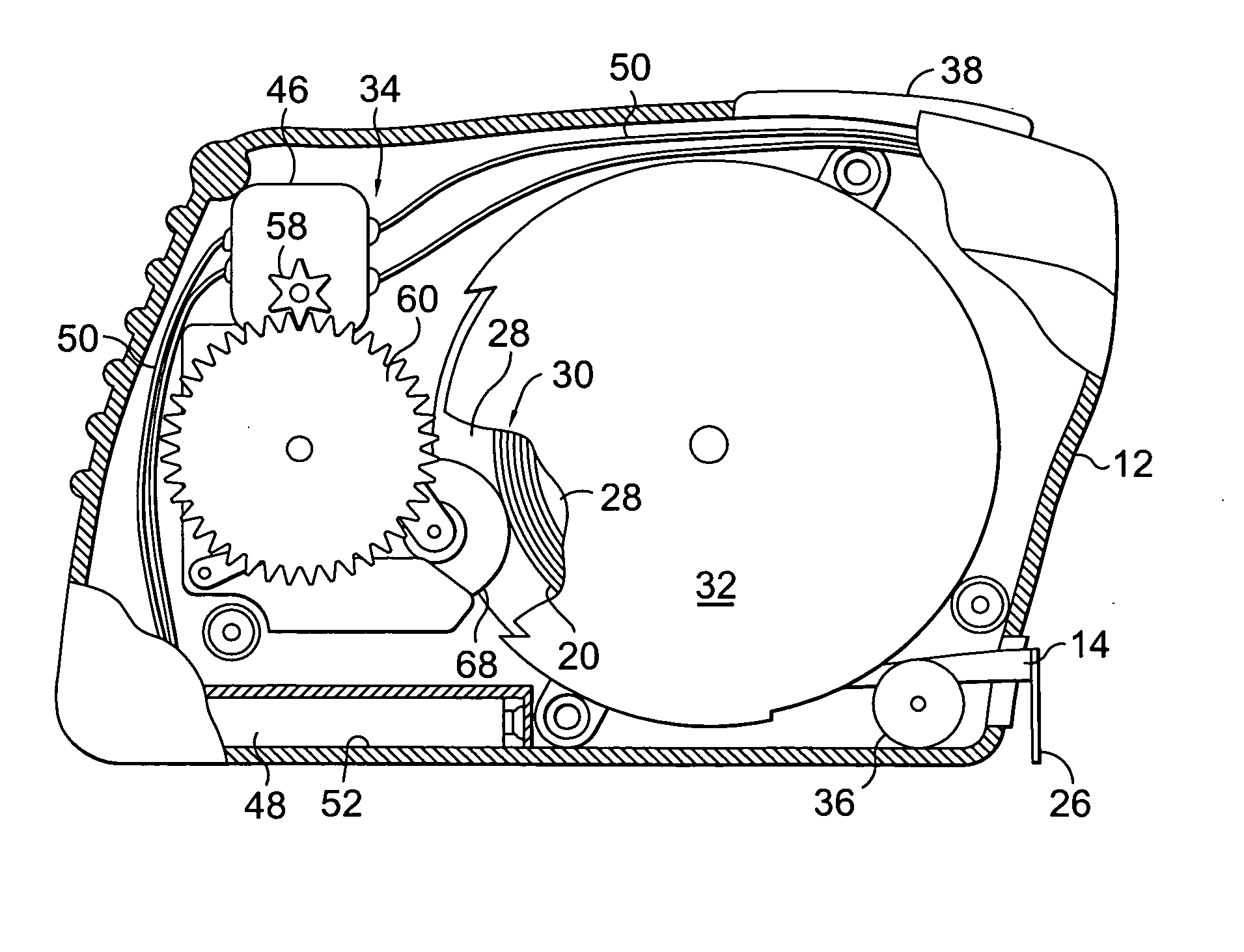
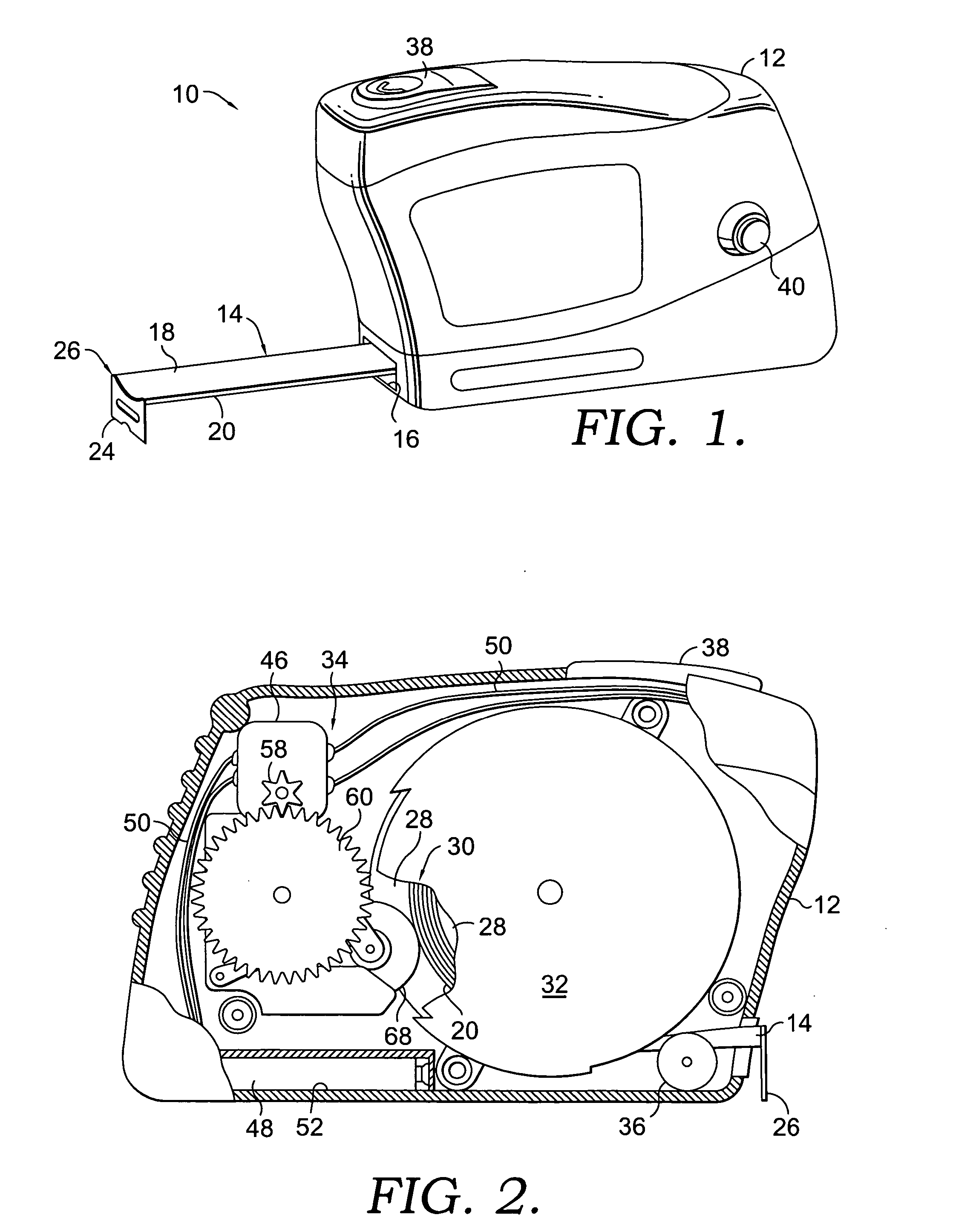
[0019] Referring now in more detail to the drawings, and initially to FIG. 1, there is illustrated an embodiment of a tape measure of the present invention designated by the reference numeral 10. The tape measure 10 has a housing shell, or housing 12, enclosing various components that control operation of the tape measure 10, as will be more fully explained below with reference to FIGS. 2-6. An elongated tape 14 having measurement indicia thereon is designed to travel through an opening 16 in the housing 12 to extend out of, and retract into, the housing 12 as needed for making a measurement of the length of an object adjacent to the tape 14. Although the tape 14 may take different forms, one conventional tape configuration suitable for integration into the tape measure 10 is for the tape 14 to take the shape of a thin blade having a top surface 18 upon which the measurement indicia is located and a bottom surface 20. A hook 24 extends downwardly from a free end 26 of the tape 14 to...


PUM


Abstract

A power operated tape measure enables extension of a tape via a drive mechanism, as well as retraction of the tape through a mechanical decoupling within the drive mechanism. The tape measure has a housing within which is positioned a spring-biased tape assembly, the drive mechanism and a clutch. The spring-biased tape assembly includes an annular reel onto which is wound a tape having indicia for taking length measurements. The drive mechanism includes a driving gear and a driven gear, and is adapted to engage with a bottom surface of the tape to extend the tape out of the housing. The clutch is adapted to displace the driven gear out of engagement with the driving gear and thereby decouple the driving and braking force provided by the drive mechanism from acting upon the bottom surface of the tape to permit the spring-biasing of the tape assembly to retract the tape into the housing.

Description

CROSS-REFERENCE TO RELATED APPLICATIONS [0001] Not applicable. STATEMENT REGARDING FEDERALLY SPONSORED RESEARCH OR DEVELOPMENT [0002] Not applicable. BACKGROUND OF THE INVENTION [0003] This invention relates generally to retractable tape measurement devices. More particularly, the present invention is directed to a tape measure employing power operated tape extension that may be disengaged for retraction of the tape back into a housing of the tape measure. [0004] Retractable tape measurement devices, or “tape measures”, are well known. These tape measures generally have a housing formed by opposed sidewalls. An aperture in the housing allows an elongated tape or “blade” having measurement indicia thereon to extend out of and retract into the housing as needed. The tape is typically wound on a reel in a coil rolled manner with the reel being rotatably mounted within the housing. A first end of the tape may be attached to the reel and second free end of the tape typically has a stop o...

Claims


Application Information

Patent Timeline
IPC IPC(8): B65H75/38B65H75/48
CPCG01B3/1005G01B2003/1028G01B2003/1048G01B2003/1046G01B2003/1043G01B3/1043G01B3/1046G01B3/1048
Inventor CAMPBELL, DAVID C.
Owner BLACK & DECKER INC
Why Eureka
Try Eureka