

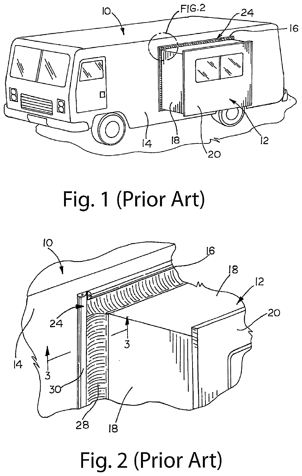
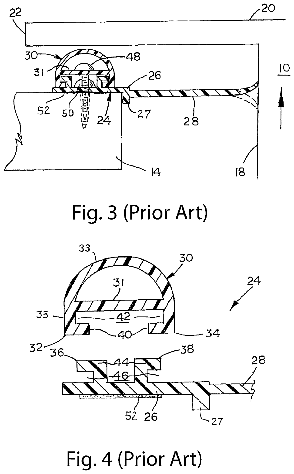
Bottom seal for use with rv slide out rooms
- Summary
- Abstract
- Description
- Claims
- Application Information
AI Technical Summary
Benefits of technology
Problems solved by technology
Method used
Image

Examples
first embodiment
[0151]a sigma seal is illustrated as sigma seal 400. As earlier described, the seal 400 has three sealing lips 402 which will abut the top phalange 406 of an RV room or the like. The sigma seal 400 also includes, at the sides thereof, concave sections 404 which will operate to collapse when the seal is squeezed between a wall or a static surface 410 and the top phalange 406. A side of the moving RV room is also shown in FIG. 27 as side 408.
[0152]Another embodiment is a U-cup 420 shown in FIG. 28. The cup 420 includes sealing positions or edges 422 and 424. An upper section 426 is provided to abut the top flange (not shown). The pressure in the interior 428 of the U-cup 420 will cause the cup to essentially inflate.
[0153]A further view of a first embodiment of the sigma seal is shown in FIG. 29 as seal 430. The seal 430 has three sealing lips 432. At an interior of the seal 430 are a set of striations 434. To seal the sigma seal 430 against a wall or static surface (not shown), a tap...
second embodiment
[0172]the bottom seal assembly 500 is described in subsequent paragraphs herein and illustrated in FIGS. 37B and 40B. This particular embodiment of the bottom seal assembly 500 is identified as bottom seal assembly 501 and is similar in structure to the bottom seal assembly 500 previously described herein and illustrated in FIGS. 32, 34, 37A and 40A. Referring again to FIGS. 37B and 40B, the assembly 501 includes a jacket 514. Jacket 514 is constructed of a rigid material in the form of a hard rubber or the like. The assembly 501 includes the main body 520 and a base 522. As with the previously-described embodiment, these components comprise the jacket 514. A bottom wipe 524 extends from an end of the base 522. The lower portion of the main body 520 and an edge of the base 522 form a right angle corner 527. A cut-away portion 525 is formed along the right angled corner 527. As with the previously-described embodiment, the jacket 514 shown in FIGS. 37B and 40B can be trimmed along th...
third embodiment
[0180]a bottom seal assembly in accordance with certain concepts of the invention is disclosed as bottom seal assembly 600 and illustrated in FIG. 37C. The bottom seal assembly 600 is similar in structure and design to the bottom seal assemblies 500 and 501 previously described herein with respect to FIGS. 37A and 37 B, respectively. In the subsequent description of bottom seal assembly 600 and FIG. 37C, components which are substantially identical in function and design to corresponding components shown in FIGS. 37A and 37B are identically numbered. Notwithstanding a similarity in structure and design among the bottom seal assemblies 500, 501 and 600, bottom seal assembly 600 differs in that the (identified in FIG. 37C as body 620) of the jacket (identified in FIG. 37C as jacket 614) is manufactured as an integral or single piece extrusion. This format 40 extrusion is also identified as unified design extrusion 696 in FIG. 37C. With this configuration, replacement of the structure ...
PUM
 Abstract
Description
Claims
Application Information