Fluxless heat spreader bonding with cold form solder

a heat spreader and cold form technology, applied in the direction of electrical equipment, semiconductor devices, semiconductor/solid-state device details, etc., can solve the problem of heat generated to levels that are unacceptabl

Inactive Publication Date: 2007-07-05
INTEL CORP
View PDF10 Cites 25 Cited by
  • Summary
  • Abstract
  • Description
  • Claims
  • Application Information

AI Technical Summary

Problems solved by technology

As the internal circuitry operates at increased clock frequencies and/or higher power levels, the amount o...

Method used


Image

  • Fluxless heat spreader bonding with cold form solder
  • Fluxless heat spreader bonding with cold form solder
  • Fluxless heat spreader bonding with cold form solder

Examples


Embodiment Construction

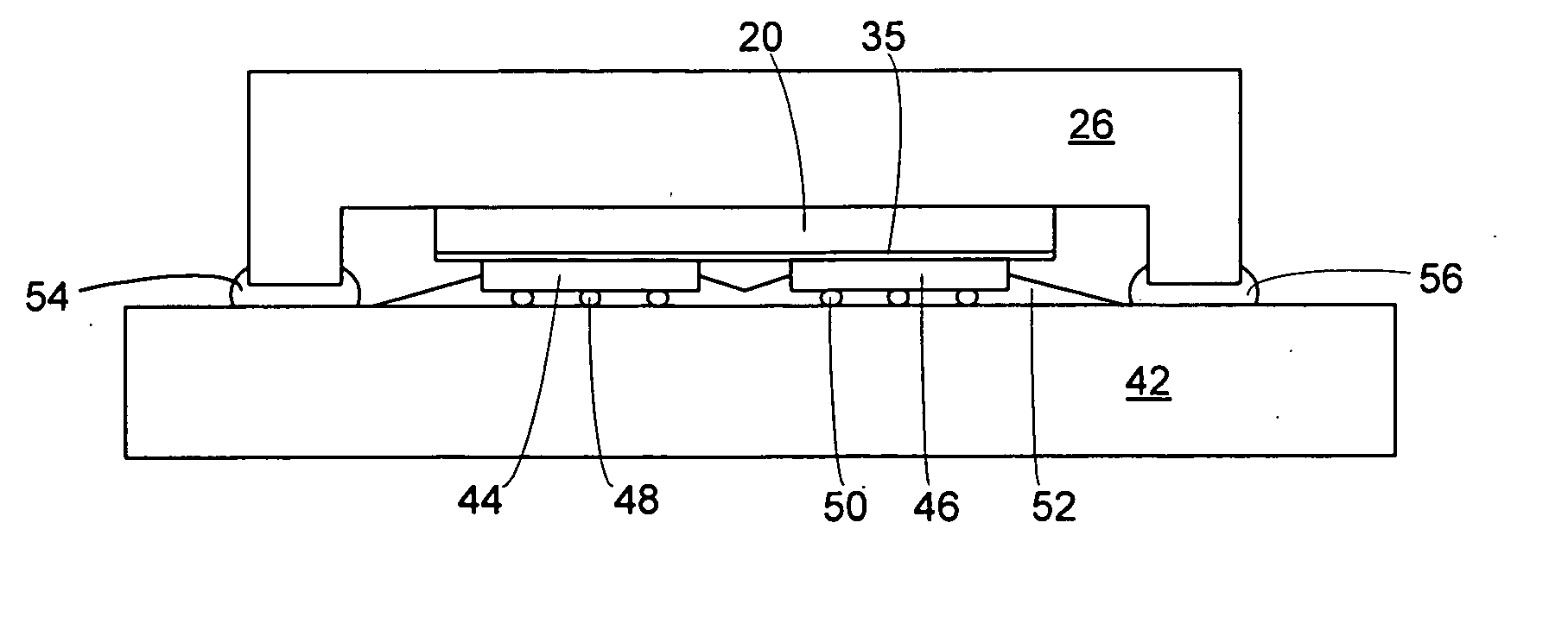
[0017] The use of flux in attaching a heat spreader to a die can lead to certain problems. The flux can cause voids in the solder thermal interface material (TIM) layer between a die and a heat spreader, and thus degrades the thermal performance and the reliability of the TIM layer joint. The use of a flux typically results in flux residue including organic compounds, present in and around the solder TIM joint. In certain types of assemblies, a heat spreader may also act as a lid over a die on a substrate. As a result, after the solder bond between the die and heat spreader lid is made, it is difficult or not possible to remove flux residue because the joint between the die and heat spreader is covered by the heat spreader and not accessible.

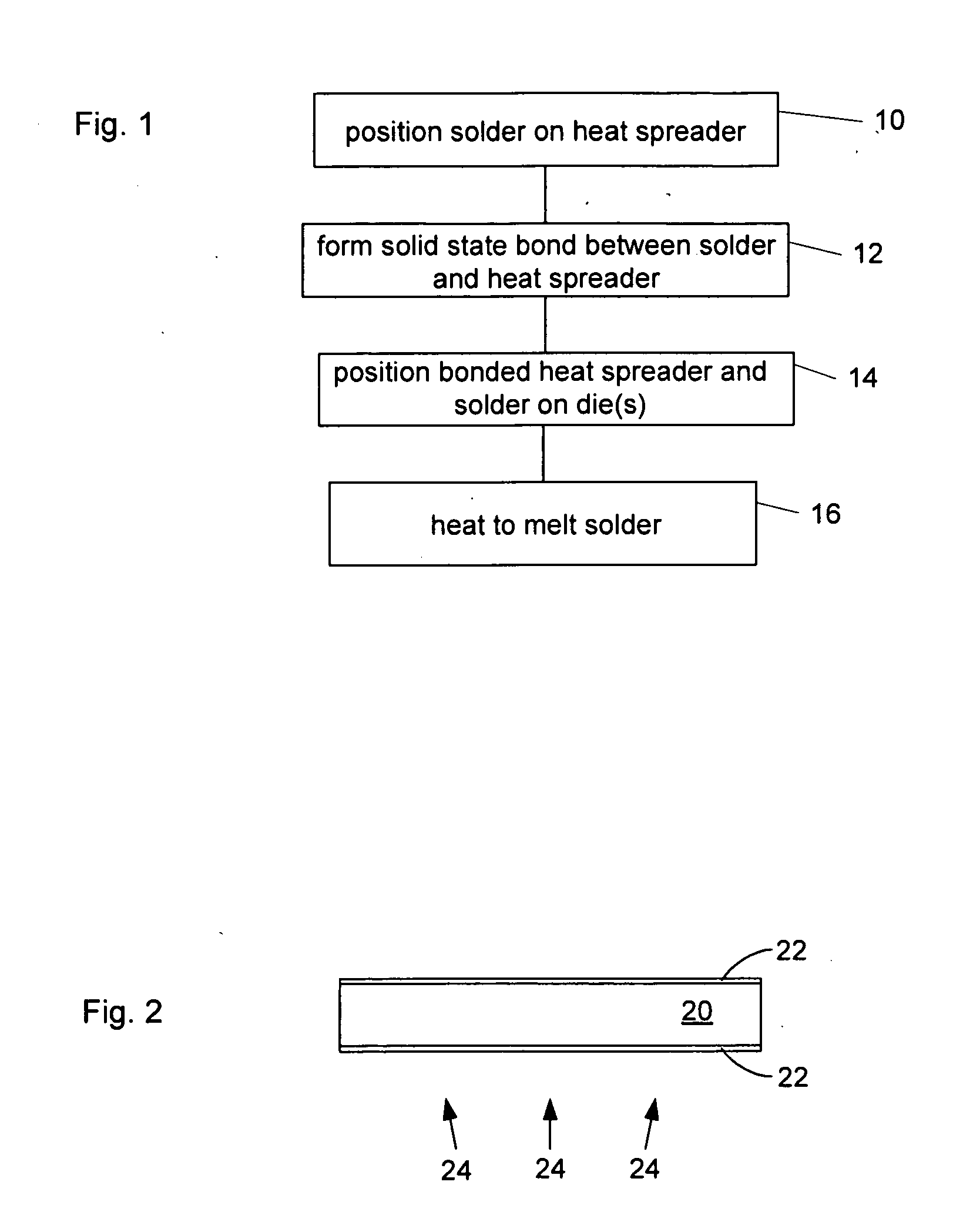
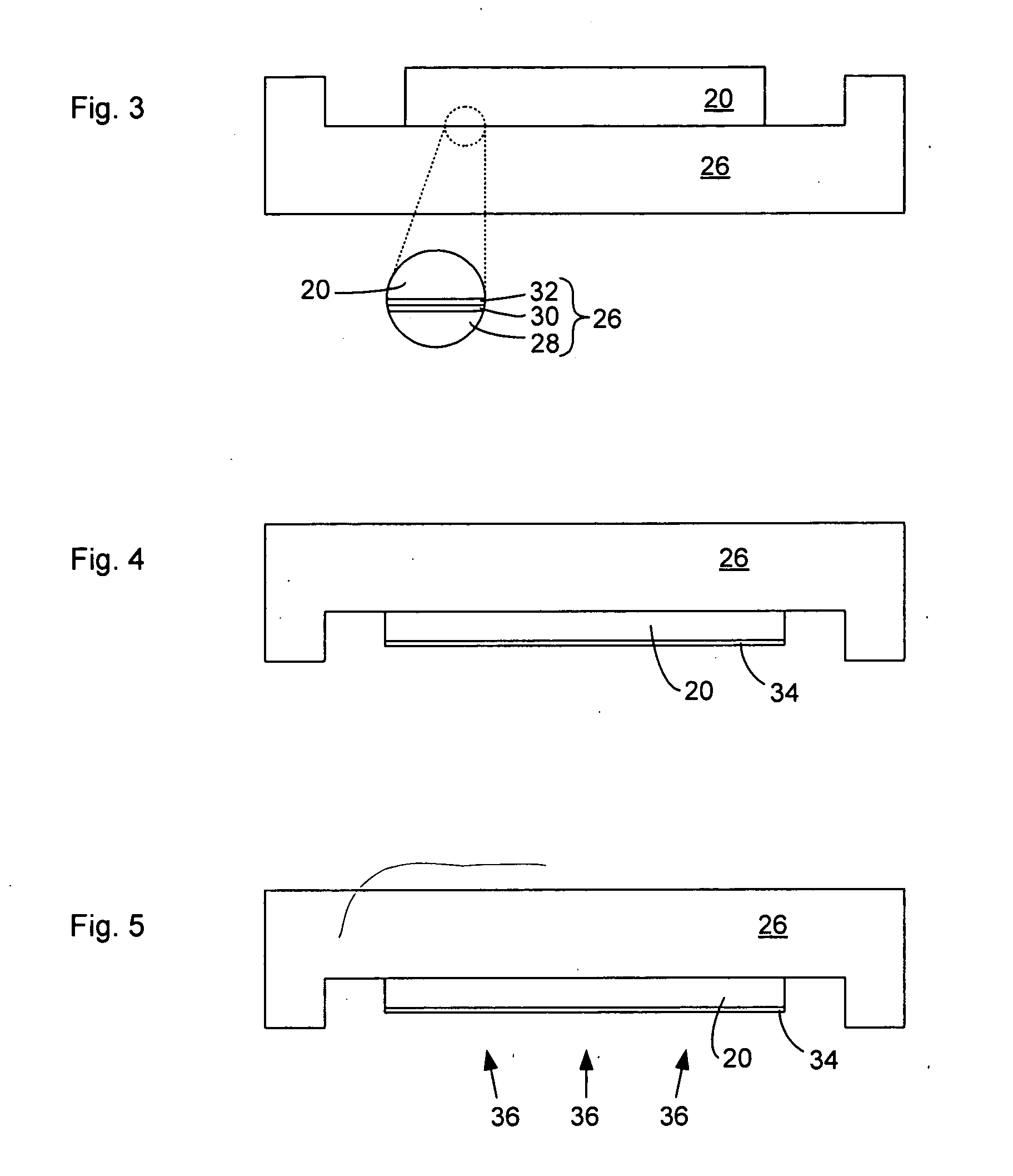
[0018] Certain embodiments relate to the formation of electronic assemblies, including fluxless attach processes for forming connections between one or more dies and a heat spreader.

[0019]FIG. 1 is a flow chart showing a number of operations i...


PUM


Abstract

The formation of electronic assemblies including a heat spreader coupled to at least one die is described. One embodiment relates to a method including positioning a solder on a heat spreader. The method also includes forming a solid state diffusion bond between the solder and the heat spreader. The solid state diffusion bonded solder and heat spreader are positioned on a die and heated to a temperature sufficient to melt the solder and form a bond between the solder and the die, in the absence of a flux. Other embodiments are described and claimed.

Description

RELATED ART [0001] Integrated circuits may be formed on semiconductor wafers that are formed from materials such as silicon. The semiconductor wafers are processed to form various electronic devices thereon. The wafers are diced into semiconductor chips (also known as dies), which may then be attached to a package substrate using a variety of known methods. In one known method for attaching a die to a substrate, the die may have solder bump contacts which are electrically coupled to the integrated circuit. The solder bump contacts extend onto the contact pads of a package substrate, and are typically attached in a thermal reflow process. Electronic signals may be provided through the solder bump contacts to and from the integrated circuit. [0002] Operation of the integrated circuit generates heat in the device. As the internal circuitry operates at increased clock frequencies and / or higher power levels, the amount of heat generated may rise to levels that are unacceptable unless som...

Claims


Application Information

Patent Timeline
IPC IPC(8): H01L23/12H01L21/50
CPCH01L21/4871H01L25/0655H01L2224/16H01L2224/73253H01L2924/01079H01L2924/16152H01L2924/01327H01L2924/00
Inventor SHI, WEILU, DAOQIANGZHOU, QINGHE, JIANGQI
Owner INTEL CORP
Why Eureka
Try Eureka