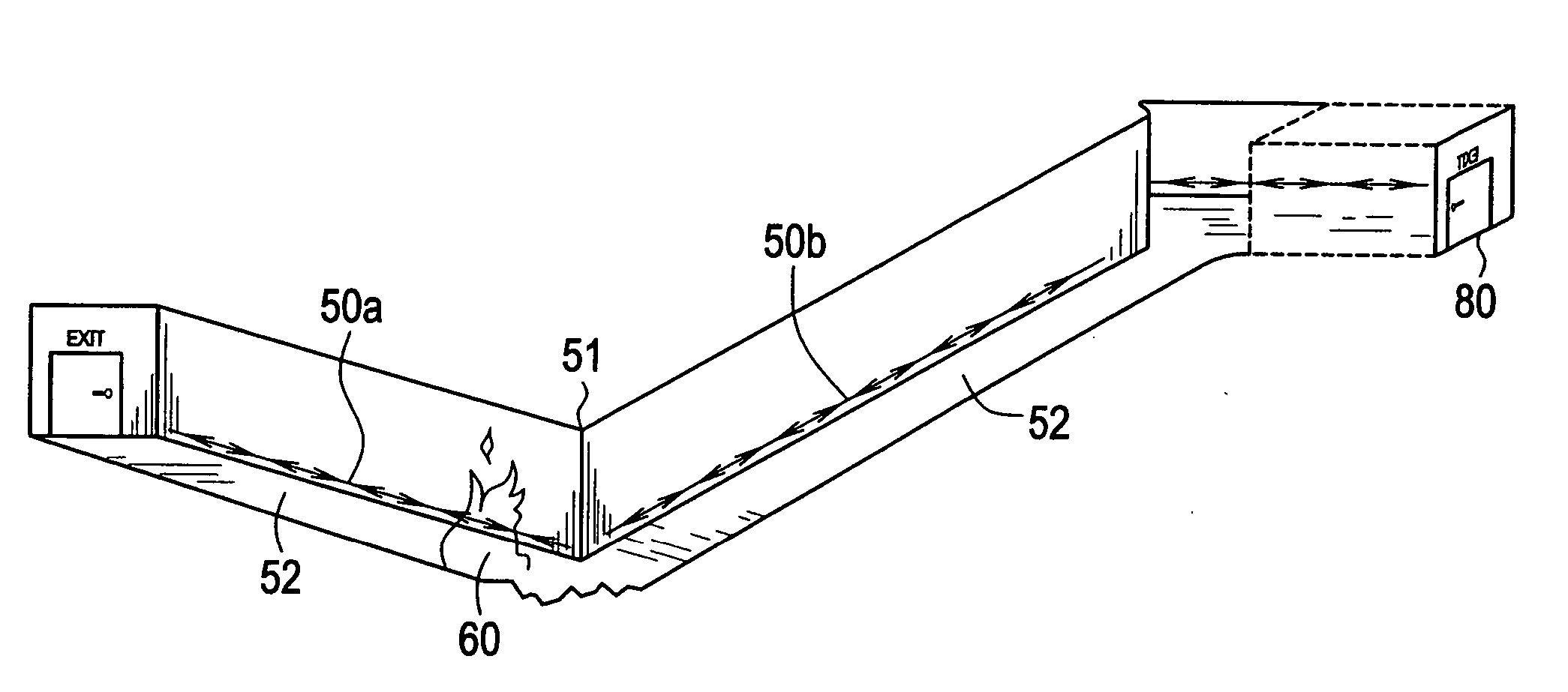
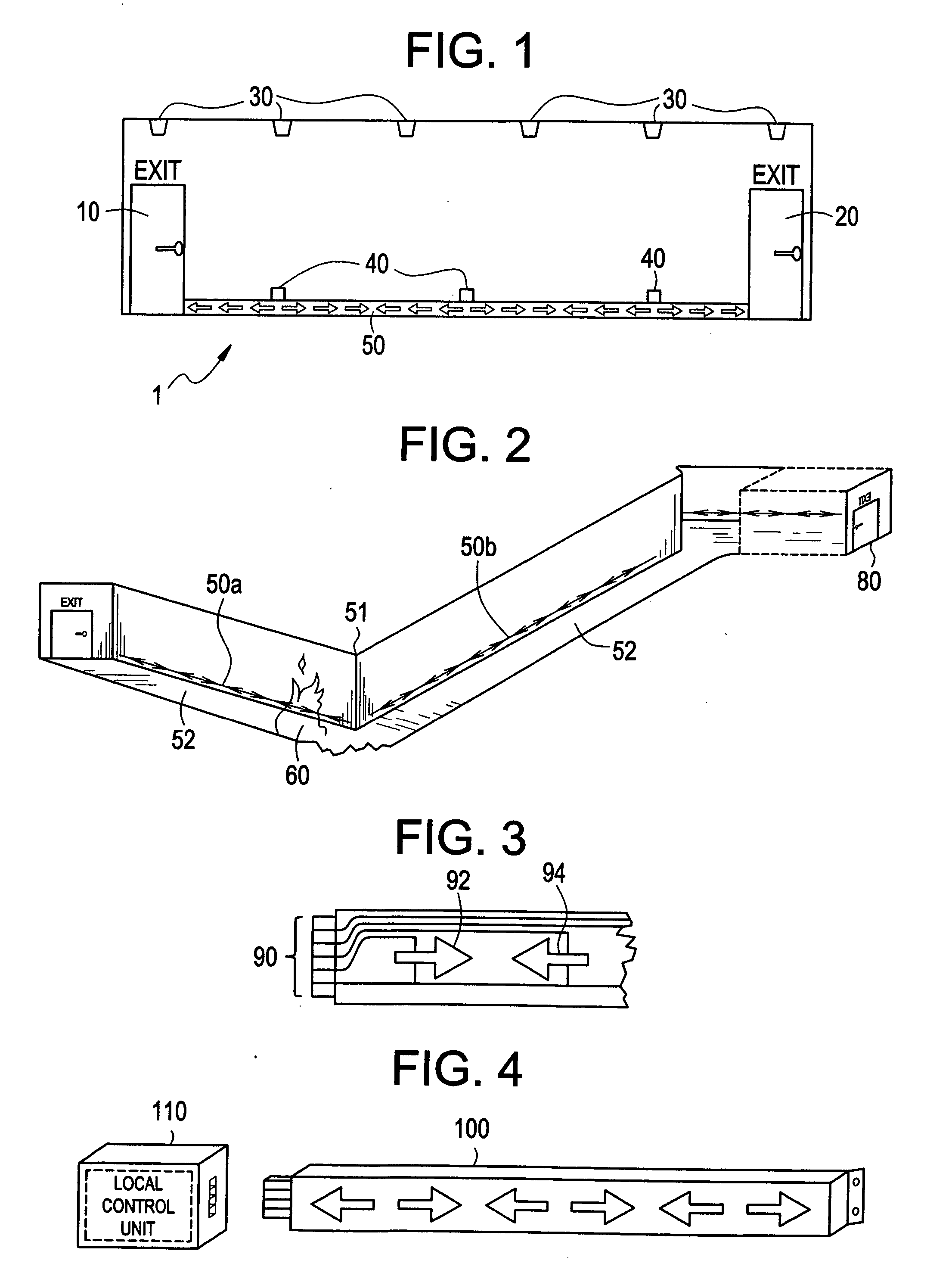
However, these systems are generally “dumb” systems that do nothing more than sound a siren or alarm to alert building occupants of a fire, (who must follow unmarked paths to an illuminated “EXIT” sign posted above an exit) and do not provide occupants and / or rescuers with useful escape information based on the relative spatial
threat of a fire.
As such, many deaths and injuries occur because of poorly marked exit paths, or because the locally mandated exit signs are obscured by
smoke and / or
darkness that typically occur during an emergency such as a fire, earthquake, explosion,
gas release, black-out, and the like.
Moreover, the presently known alarm systems are both expensive and difficult to produce, install and maintain, and often do not address a variety of
emergency situations other than fires.
Furthermore, exit lamps that are used in conjunction with conventional fire alarm systems consume excessive power from battery operated emergency power supply systems and therefore fail to effectively produce sufficient light after an initial period of operation.
In addition, conventional exit lamps are unreliable because they can unpredictably
burn out at the time of emergency use.
In addition, the indication lamps and arrangements in conventional systems are difficult to see and understand during
emergency situations.
Conventional systems also fail to provide information about alternative routes of egress.
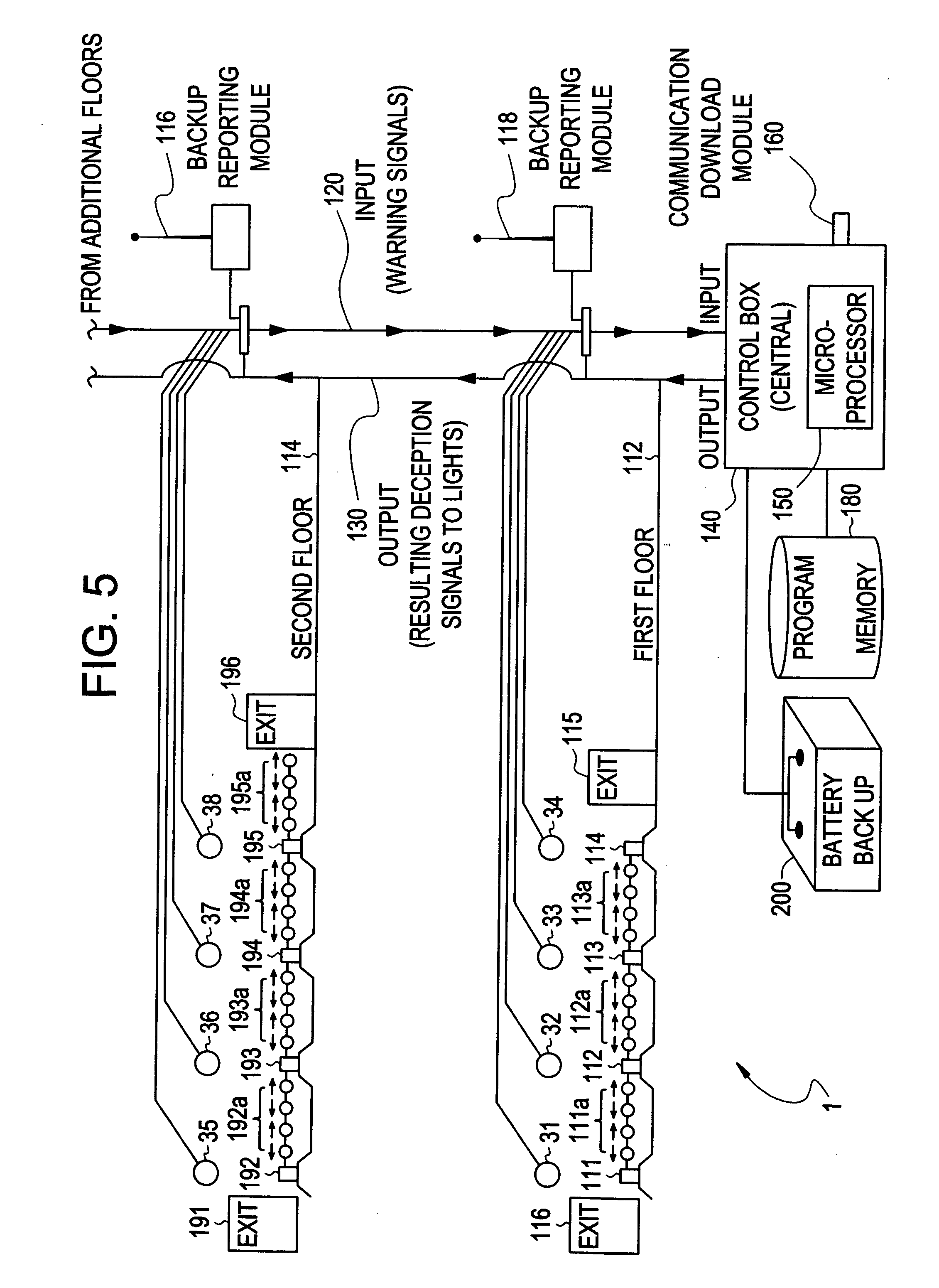
Nevertheless, there have been attempts in the prior art to overcome some of these problems in directing evacuees to exits, but none provide a means to direct evacuees from all areas and floors of a building away from the direction of a fire reported by a fire alarm
system.
These types of systems, however, do not offer panicked evacuees a clear
sense of direction, given that a
laser may point from say, point A to Point B, but cannot show whether one should proceed towards point A, rather than point B, or vice-versa.
Even where such systems attempt to point to a direction by decreasing the slope from say, high to low along the length of a space, for long lengths of corridors, this method does not work as well as in smaller confines.
In any case, however, this approach is fraught with shortcomings in that it is not an immediately obvious, fool-proof means of directing evacuees toward an exit, especially if such evacuees have not been already instructed in the interpretation of such
laser points.
However, this approach too, is not immediately intuitive to panicked evacuees who may not understand the meaning of sequenced columns of vertical lights throughout corridors.
However, Minter, does not provide a solution for such notification on a wholesale, building- level approach that can be used to reflect the danger to occupants on other floors / areas from a fire on a different floor / area.
Moreover, Minter does not allow for a
system that can provide real-time, large-scale intelligence to firemen and other responders to the scene of an alarm.
Accordingly, none of the other systems in the prior art provide a solution to indicate the safest exit in a universally understandable, intuitive manner such that all evacuees, anywhere in a building, can immediately grasp the correct direction towards an exit relative to a fire (or fires), wherever it (and they) may be located.
In addition, none of the prior art offers intelligent output from such a
system, so that firemen and responders can accurately understand the scope of the emergency at hand.

