
Intelligent antenna

a technology of intelligent antennas and antennas, applied in antenna arrays, electrical devices, antennas, etc., can solve the problems of insignificant improvement in signal receiving quality, increased antenna area, and even smaller area for mounting antennas on the circuit board of wireless transceivers, so as to achieve optimal signal receiving quality and eliminate dead angle problems

Inactive Publication Date: 2007-07-05
ALPHA NETWORKS INC
View PDF2 Cites 8 Cited by
  • Summary
  • Abstract
  • Description
  • Claims
  • Application Information

AI Technical Summary

Benefits of technology

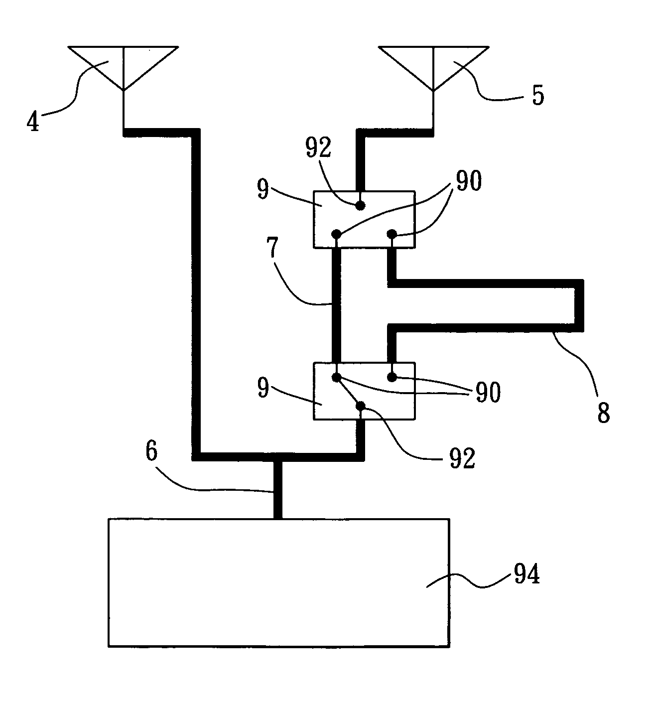
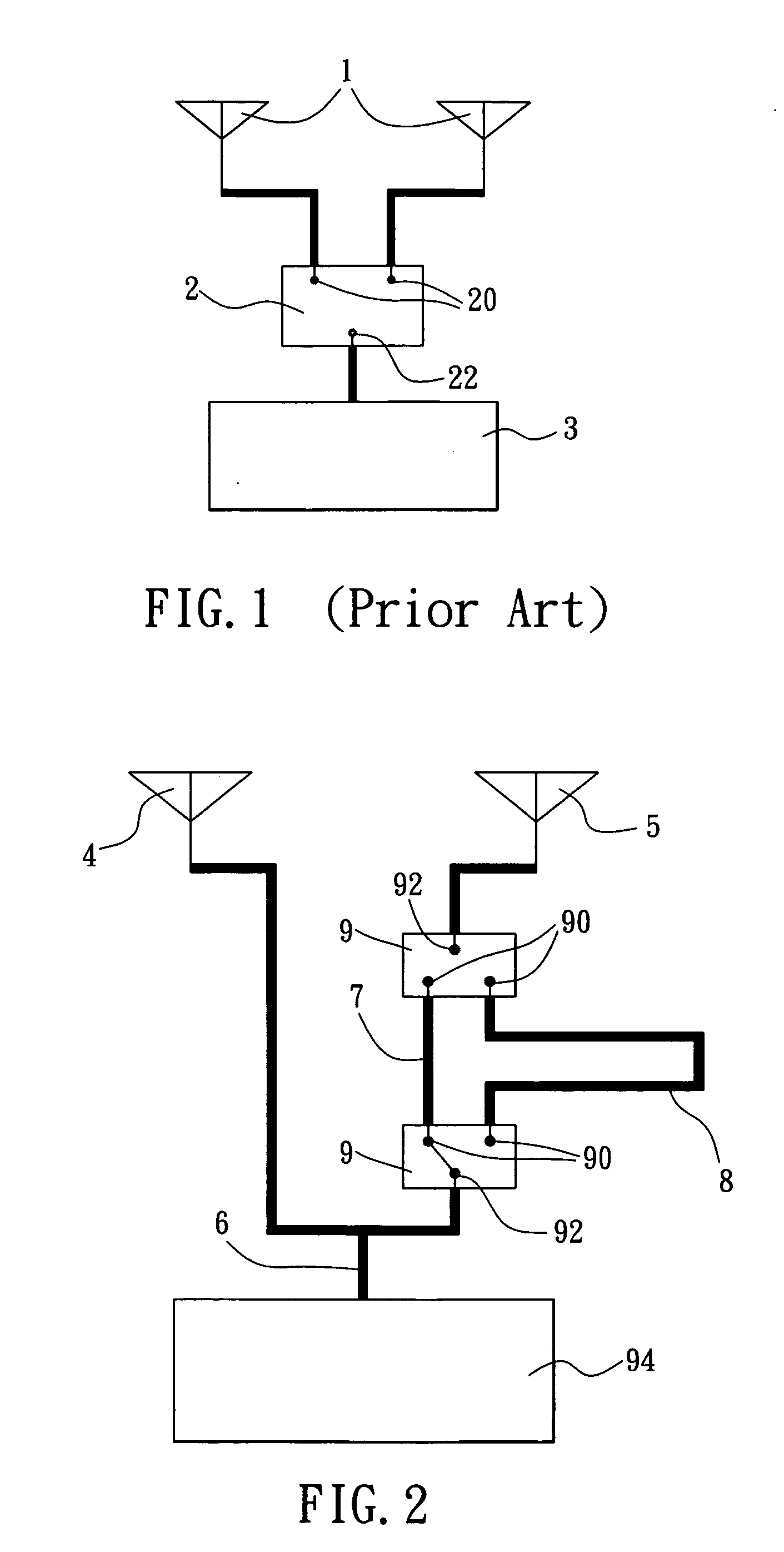
The present invention provides an intelligent antenna that overcomes the drawbacks of prior art. It includes an antenna diversity transceiver circuit connected to a T-shaped connecting member with two antenna units. The antenna diversity signal is sent through either the first or second transmission line to optimize signal receiving quality. The intelligent antenna eliminates dead angle problem and improves signal quality by utilizing both antenna units simultaneously.

Problems solved by technology

However, area for mounting antenna on the circuit board of a wireless transceiver becomes even smaller.
The antenna area is further limited since there are many components and mechanisms are mounted in the circuit board of the wireless transceiver.
However, signal receiving quality has not improved significantly.

Method used


Image

  • Intelligent antenna
  • Intelligent antenna
  • Intelligent antenna

Examples


Embodiment Construction

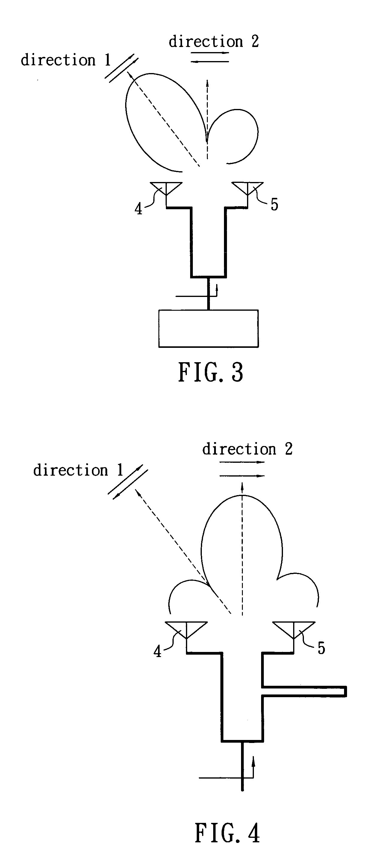
[0014] Referring to FIG. 2, an intelligent antenna in accordance with a preferred embodiment of the invention is mounted on a circuit board of a device. The antenna comprises a first antenna unit 4, a second antenna unit 5, a T-shaped connecting member 6, a first transmission line 7, a second transmission line 8, and two radio frequency switches 9. Each component is discussed in detailed below. The first antenna unit 4 is connected to a first end of the T-shaped connecting member 6 and the second antenna unit 5 is connected to a second end of the T-shaped connecting member 6 in which the first and second ends of the T-shaped connecting member 6 are symmetric about a third end thereof. Thus, a two-element antenna array consisting of the antenna units 4 and 5 and the T-shaped connecting member 6 is formed. The third end of the T-shaped connecting member 6 is a joining end of the two-element antenna array and an antenna diversity transceiver circuit 94 provided on the circuit board. Si...


PUM


Abstract

The present invention is to provide an intelligent antenna mounted on a circuit board including an antenna diversity transceiver circuit connected to an intermediate third end of a T-shaped connecting member, and a first and a second antenna units connected to two symmetric ends of the T-shaped connecting member respectively, wherein two radio frequency switches are interconnected the second antenna unit and one of the two symmetric ends through two transmission lines respectively. Thus, an antenna diversity signal sent from the antenna diversity transceiver circuit is adapted to switch both the radio frequency switches so as to direct signal from the second antenna unit to the T-shaped connecting member through the two transmission lines, which are adapted to generate a phase difference either in-phase or out-of-phase between signals sent from the first and second antenna units, in order to obtain an optimum signal receiving quality for the intelligent antenna and eliminate dead angle problem caused by antenna radiation field.

Description

FIELD OF THE INVENTION [0001] The present invention relates to antenna structure and more particularly to an intelligent antenna having a T-shaped connecting member to connect a first and a second antenna units and form an antenna array, wherein two radio frequency switches are interconnected the second antenna unit and one of two symmetric ends of T-shaped connecting member through two transmission lines respectively, enabling the first and second antenna units to be utilized to obtain an optimum signal receiving quality for the intelligent antenna. BACKGROUND OF THE INVENTION [0002] Currently, a wireless transceiver is required to have multiple antenna for preventing dead angles from occurring in sending and receiving the electromagnetic waves as stipulated in WLAN (wireless local area network) standard. Hopefully, received signal quality can be optimum. [0003] There is a trend of downsizing wireless transceivers in the manufacturing of the art. However, area for mounting antenna ...

Claims


Application Information

Patent Timeline
Patent Type & Authority Applications(United States)
IPC IPC(8): H01Q3/24
CPCH01Q3/34
Inventor YEH, MING-HAO
Owner ALPHA NETWORKS INC
Learn More