
Portable paraboloid satellite earth antenna capable of being rapidly erected and folded

A satellite receiving, portable technology, applied in the direction of antenna, antenna support/installation device, electrical components, etc., can solve the problems of poor stability, uncompactness, large gap between structural parts, etc., to improve the quality of signal reception, the occupation The effect of minimizing space and ensuring reliability

Active Publication Date: 2013-06-12
SICHUAN HUSHAN ELECTRIC APPLIANCE +1
View PDF4 Cites 2 Cited by
  • Summary
  • Abstract
  • Description
  • Claims
  • Application Information

AI Technical Summary

Problems solved by technology

[0002] In the prior art, a small parabolic satellite receiving antenna is mainly composed of an antenna reflection panel, a support adjustment mechanism for the antenna reflection panel, a feed source tuner assembly, and a support adjustment mechanism for the feed source tuner assembly; There are two ways to use it: type and integral type; when using a split-type small parabolic satellite receiving antenna, since the various supports, connectors, and fasteners that make up the parabolic satellite receiving antenna are scattered in the packaging box, the user needs to use it according to the usage. The manual assembles various parts, and the assembly and erection will take a long time, especially when used in the field with frequent transitions, the assembly and disassembly are complicated and troublesome, and the parts are easy to lose, which is very inconvenient to use; it adopts an integral small parabolic satellite receiving antenna In the field, without dismantling and directly packing into the box to transfer the site, the height of the box can reach more than 350mm (take the 45Cm antenna as an example), which takes up a lot of space, and is easy to cause damage to the antenna, and it is still very inconvenient to use; in addition, The various structural parts of the existing small parabolic satellite receiving antenna have a large fit gap, poor integrity, poor stability after assembly, and the feed source is more likely to shake due to external force, which greatly affects the quality of the received signal and positioning accuracy. Compact, cumbersome to assemble, disassemble and debug, poor practicability

Method used


Image

  • Portable paraboloid satellite earth antenna capable of being rapidly erected and folded
  • Portable paraboloid satellite earth antenna capable of being rapidly erected and folded
  • Portable paraboloid satellite earth antenna capable of being rapidly erected and folded

Examples


Embodiment 1

[0033] Embodiment 1: refer to each accompanying drawing.

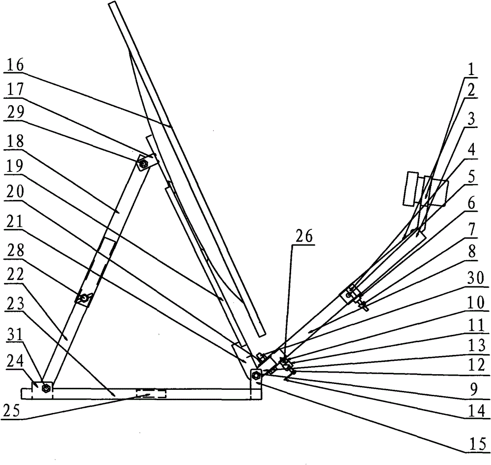
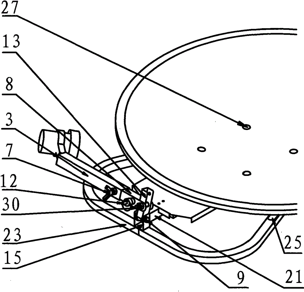
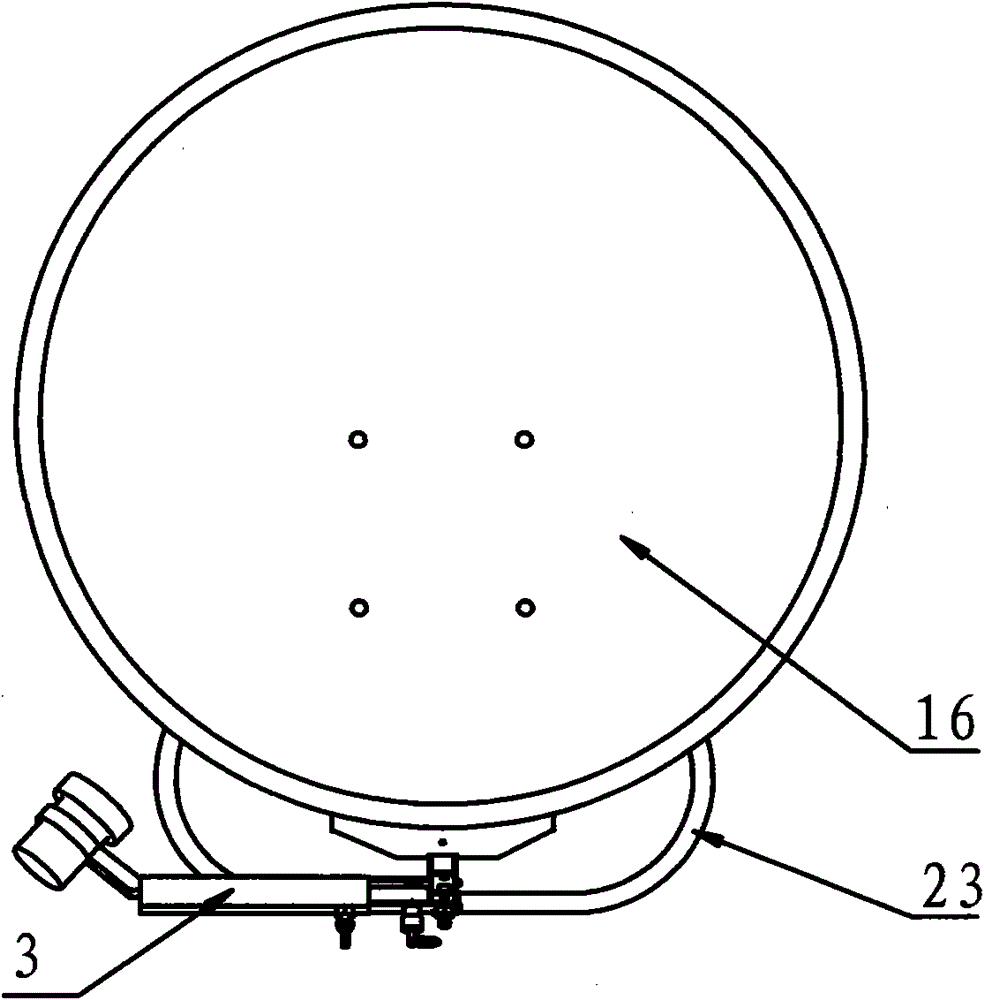
[0034] A portable parabolic satellite receiving antenna that can be quickly erected and folded, mainly composed of: antenna reflection panel 16, support adjustment mechanism of antenna reflection panel, feed source tuner assembly 1, and support adjustment mechanism of feed source tuner assembly composition;

[0035] The support adjustment mechanism of the antenna reflection panel includes:

[0036] Chassis 23, a first bracket 15 fixedly connected or integrated with one end of the chassis 23, and a second bracket 24 fixedly connected or integrated with the other end of the chassis 23;

[0037] The support plate 19 fixedly connected with the antenna reflection panel 16, the third bracket 17 fixedly connected or integrated with one end of the support plate 19, the third support 17 fixedly connected or integrated with the other end of the support plate 19, and the other end passes through A positioning bracket 21 in which ...

Embodiment 2

[0042] Embodiment 2: refer to each accompanying drawing.

[0043] A portable parabolic satellite receiving antenna that can be quickly erected and folded, mainly composed of: antenna reflection panel 16, support adjustment mechanism of antenna reflection panel, feed source tuner assembly 1, and support adjustment mechanism of feed source tuner assembly composition;

[0044] The support adjustment mechanism of the antenna reflection panel includes:

[0045] Chassis 23, a first bracket 15 fixedly connected or integrated with one end of the chassis 23, and a second bracket 24 fixedly connected or integrated with the other end of the chassis 23;

[0046] The support plate 19 fixedly connected with the antenna reflection panel 16, the third bracket 17 fixedly connected or integrated with one end of the support plate 19, the third support 17 fixedly connected or integrated with the other end of the support plate 19, and the other end passes through A positioning bracket 21 in whic...


PUM


Abstract

The invention provides a portable paraboloid satellite earth antenna capable of being rapidly erected and folded, which mainly comprises an antenna reflection panel, a supporting and adjusting mechanism of the antenna reflection panel, a feed source tuner assembling unit and a supporting and adjusting mechanism of the feed source tuner assembling unit. The antenna is characterized in that the supporting and adjusting mechanism of the antenna reflection panel comprises a chassis, a first support, a second support, a facing bar, a third support, a locating support, an elevation regulating stem lower part, an elevation regulating stem upper part and a first dished lock-screw, wherein the first support and the second support are fixedly connected with the chassis; the facing bar is fixedly connected with the antenna refection panel, the third support is fixedly connected with the facing bar, one end of the locating support is fixedly connected with the facing bar and the other end of the locating support is flexibly connected with the first support; and the elevation regulating stem lower part is flexibly connected with the second support, one end of the elevation regulating stem upper part is flexibly connected with the third support, the other end of the elevation regulating stem upper part is flexibly sheathed with the elevation regulating stem lower part, and the first dished lock-screw is connected with the elevation regulating stem upper part. The invention is especially suitable for temporary sites and outdoor sites and has the advantages of compact structure, rapid andflexible erection and folding, convenient carrying and strong practical applicability.

Description

technical field [0001] The invention belongs to a parabolic antenna device, and relates to a portable parabolic satellite receiving antenna which can be erected and folded quickly. It is especially suitable for small (45cm and below) satellite antennas used in mobile and field places. Background technique [0002] In the prior art, a small parabolic satellite receiving antenna is mainly composed of an antenna reflection panel, a support adjustment mechanism for the antenna reflection panel, a feed source tuner assembly, and a support adjustment mechanism for the feed source tuner assembly; There are two ways to use it: type and integral type; when using a split-type small parabolic satellite receiving antenna, since the various supports, connectors, and fasteners that make up the parabolic satellite receiving antenna are scattered in the packaging box, the user needs to use it according to the usage. The manual assembles various parts, and the assembly and erection will tak...

Claims


Application Information

Patent Timeline
Patent Type & Authority Patents(China)
IPC IPC(8): H01Q1/12H01Q15/16H01Q19/12
Inventor 汪敏文庞礴
Owner SICHUAN HUSHAN ELECTRIC APPLIANCE
Learn More