Liquid crystal display device and driving method thereof

a liquid crystal display and driving method technology, applied in the field of display devices, can solve the problems of motion blurring phenomenon, degrade image quality, and more serious degradation of image quality, so as to prevent motion blur, improve image quality, and improve image quality

Inactive Publication Date: 2007-07-05
LG DISPLAY CO LTD
View PDF6 Cites 61 Cited by
  • Summary
  • Abstract
  • Description
  • Claims
  • Application Information

AI Technical Summary

Benefits of technology

[0017]An object of embodiments of the present invention is to provide an LCD that can improve the image quality by preventing motion blur.
[0018]Another object of embodiments of the present invention is to provide a method of driving an LCD that can improve the image quality by preventing motion blur.
[0019]Another object of embodiments of the present invention is to provide an LCD that can improve the image quality by preventing image-sticking.
[0020]Another object of embodiments of the present invention is to provide a method of driving an LCD that can improve the image quality by preventing image-sticking.

Problems solved by technology

When displaying a moving picture, such a hold-type LCD cannot cope with the rapid image changes and a motion blurring phenomenon occurs.
Consequently, an unclear image or image-sticking occurs in the LCD, which degrades image quality.
During the alignment saturation period, the liquid crystal cells cannot correctly display the pixel data, thereby causing a motion blurring phenomenon and a more serious degradation of the image quality.

Method used


Image

  • Liquid crystal display device and driving method thereof
  • Liquid crystal display device and driving method thereof
  • Liquid crystal display device and driving method thereof

Examples


first embodiment

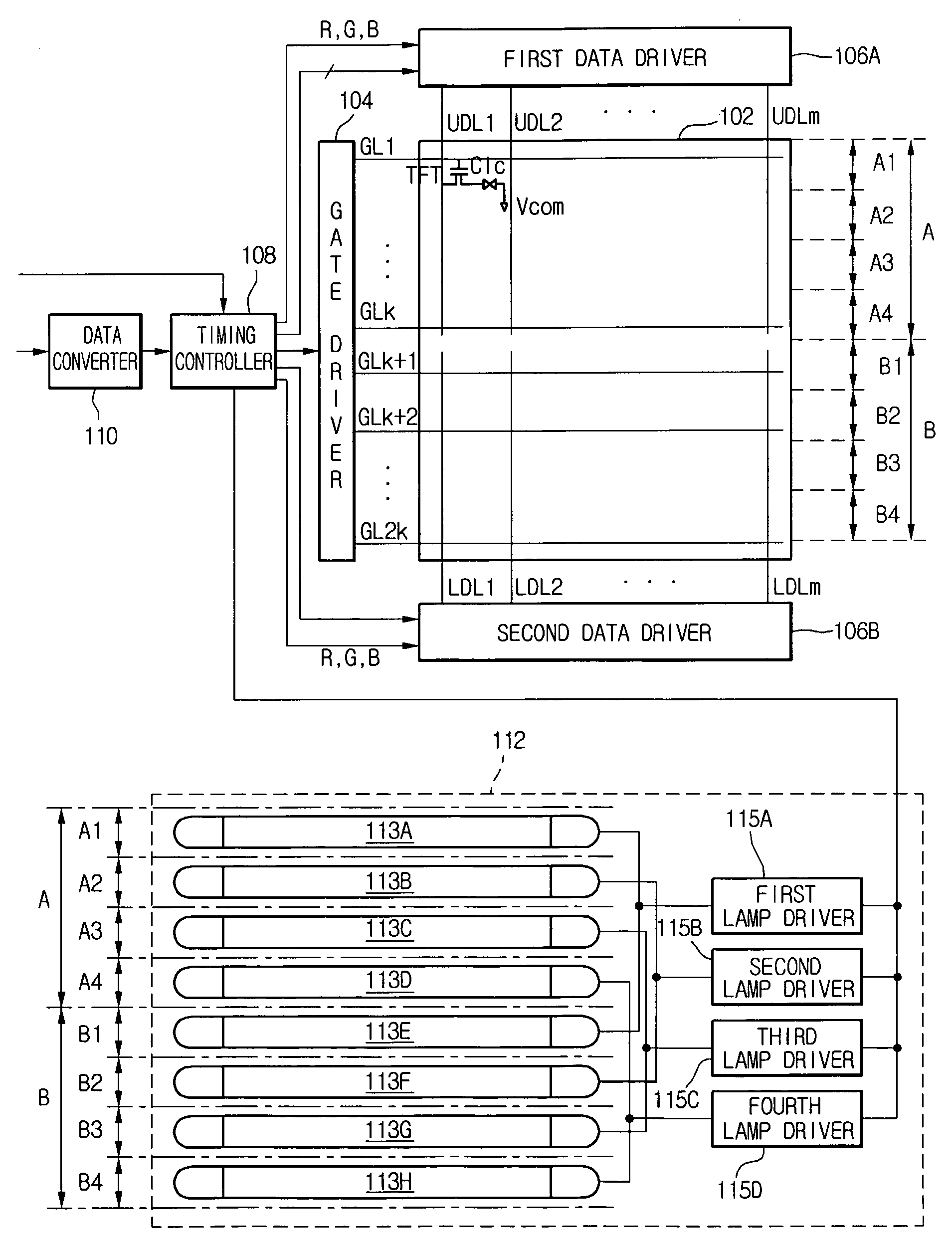
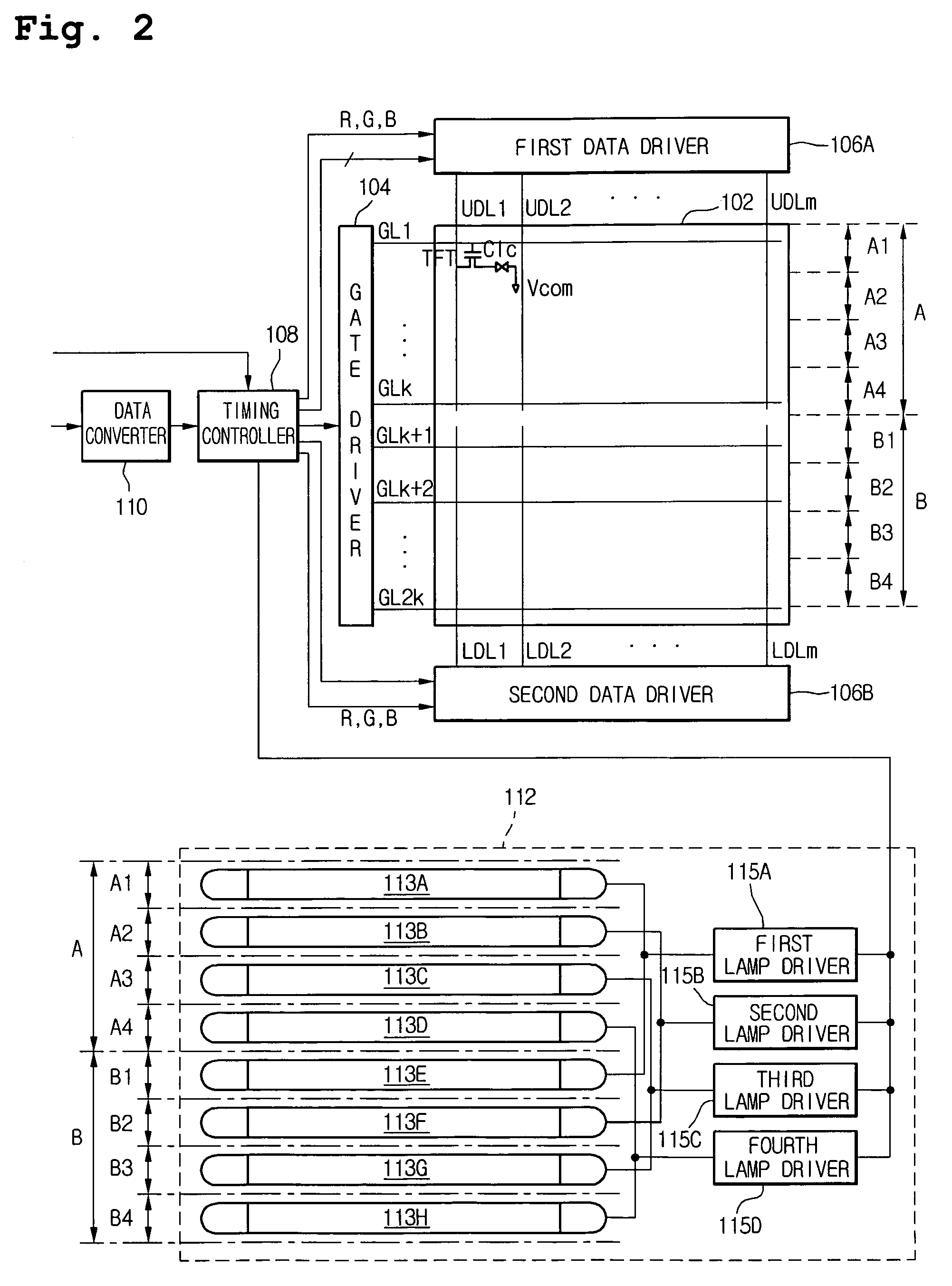
[0044]FIG. 2 is a schematic diagram of an LCD according to the present invention. As shown in FIG. 2, the LCD includes a liquid crystal panel 102 for displaying an image, a gate driver 104 for driving a plurality of gate lines GL1-GL2k on the liquid crystal panel 102, a first data driver 106A for driving a plurality of upper data lines UDL1-UDLm formed on the liquid crystal panel 102, and a second data driver 106B for driving a plurality of lower data lines LDL1-LDLm on the liquid crystal panel 102.

[0045]The upper data lines UDL1-UDLm are arranged on an upper portion A of the liquid crystal panel 102 and cross a first k number of gate lines GL1-GLk arranged in a vertical direction. The lower data lines LDL1-LDLm are arranged on a lower portion B of the liquid crystal panel 102 and cross a second k number of gate lines GL(k+1)-GL2k arranged in a vertical direction. TFTs, acting as switching elements, are formed at crossings of the gate lines GL1-GL2k and the upper and lower data line...

second embodiment

[0061]FIG. 4 is a schematic diagram of an LCD according to the present invention. Referring to FIG. 4, the LCD includes a first gate driver 204A for driving a plurality of left gate lines LGL1-LGL2k disposed on the left of the liquid crystal panel 202, a second gate driver 204B for driving a plurality of right gate lines RGL1-RGL2k disposed on the right of the liquid crystal panel 202, and a data driver 206 for driving a plurality of data lines DL1-DL2j disposed on the liquid crystal panel 202.

[0062]The left gate lines LGL1-LGL2k are arranged on a left portion C of the liquid crystal panel 202 and cross a first j number of data lines DL1 to DLj arranged in a horizontal direction. The right gate lines RGL1-RGL2k are arranged on a right portion D of the liquid crystal panel 202 and cross a second j number of data lines DL(j+1)-DL2j arranged in a horizontal direction. TFTs acting as switching elements are formed at crossings between the data lines DL1-DL2j and the left and right gate l...

third embodiment

[0078]FIG. 6 is a schematic diagram of a Line On Glass (LOG) type LCD according to the present invention. Referring to FIG. 6, the LCD includes a liquid crystal panel 302 for displaying an image, a plurality of data tape carrier packages (TCPs) 318a to 318c connected between the liquid crystal panel 302 and a data printed circuit board (PCB) 320, a plurality of gate TCPs 316a to 316d provided at one side and another side of the liquid crystal panel 302, a plurality of data driver ICs 306a to 306c mounted on the data TCPs 318a to 318c, and a plurality of gate driver ICs 304a to 304d mounted on the gate TCPs 316a to 316d. The liquid crystal panel 302 includes a lower substrate 311, an upper substrate 313, and a liquid crystal (not shown) injected between the lower substrate 311 and the upper substrate 313. The lower substrate 311 and the upper substrate 313 are transparent insulation substrates. Among the plurality of gate TCPs 316a to 316d, the first and second gate TCPs 316a and 316...


PUM


Abstract

A liquid crystal display device includes a liquid crystal panel having first data lines crossing gate lines on a first region of the liquid crystal panel and second data lines crossing the gate lines on a second region of the liquid crystal panel; a data converter for converting a first video data having a first frame frequency into a second video data having a second frame frequency, which is higher than the first frame frequency; a backlight unit having a first lamp group with at least two lamps for respectively irradiating light onto sub-regions of the first region and a second lamp group with at least two lamps respectively irradiating light on sub-regions of the second region; and a driver for driving the gate lines, the first data lines and the second data lines in accordance with the second video data and for driving the first and second lamp groups at the second frame frequency so that the lamps of the first lamp group are sequentially turned on and off in synchronization with the lamps of the second lamp group.

Description

[0001]This application claims the benefit of the Korean Patent Application Nos. 10-2005-0132789, filed on Dec. 29, 2005, and 10-2006-080887, filed on Aug. 25, 2006, both of which are hereby incorporated by reference in their entirety.BACKGROUND OF THE INVENTION[0002]1. Field of the Invention[0003]Embodiments of the present invention relates to a display device, and more particularly, to a liquid crystal display device and a driving method thereof. Embodiments of the present invention are suitable for a wide scope of applications. In particular, some embodiments are suitable for preventing image-sticking and / or image blur.[0004]2. Description of the Related Art[0005]As the information society develops, demand for various flat panel display devices is increasing. To meet such a demand, flat panel display devices, such as liquid crystal display device (LCD), plasma display panel (PDP), and electroluminescent display (ELD), have been developed. In particular, LCDs are lightweight, slim ...

Claims


Application Information

Patent Timeline
Patent Type & Authority Applications(United States)
IPC IPC(8): G09G3/36
CPCG09G3/342G09G3/3666G09G2330/021G09G2320/0257G09G2320/0233
Inventor AHN, JI YOUNG
Owner LG DISPLAY CO LTD
Why Eureka
Try Eureka