Inkjet image forming apparatus and control method of the same

Inactive Publication Date: 2007-07-05
SAMSUNG ELECTRONICS CO LTD
View PDF8 Cites 41 Cited by
  • Summary
  • Abstract
  • Description
  • Claims
  • Application Information

AI Technical Summary

Benefits of technology

[0031]The control unit may store constant values corresponding to the first, second, and third predetermined distances. The control unit may synchronize the ejection of the ink by the plurality of first nozzles and the plurality of second nozzles using the constant values. The control unit may continuously update the constant values to precisely align ink dots ejected by the first and second printheads onto the printing medium. The control unit may update the constant values during predetermined time periods to precisely align ink dots ejected by the first and second printheads

Problems solved by technology

However, since the array type ink cartridge cannot move in the main scanning direction, the print quality of the array type ink cartridge is negatively affected by defective nozzles, and it is difficult to compensate for the defective nozzles.
Further, since it is difficult to structurally increase a nozzle density of the array type ink cartridge in the main scanning direction, a print resolution of the array type ink cartridge is relatively low.
Therefore, if some of the nozzles are defective due to electrical or mechanical damage, the ink is not normally fired.
When the array type ink cartridge prints an image on the printing medium, the defective nozzles cause whit

Method used


Image

  • Inkjet image forming apparatus and control method of the same
  • Inkjet image forming apparatus and control method of the same
  • Inkjet image forming apparatus and control method of the same

Examples


Embodiment Construction

[0049]Reference will now be made in detail to the embodiments of the present general inventive concept, examples of which are illustrated in the accompanying drawings, wherein like reference numerals refer to the like elements throughout. The embodiments are described below in order to explain the present general inventive concept by referring to the figures.

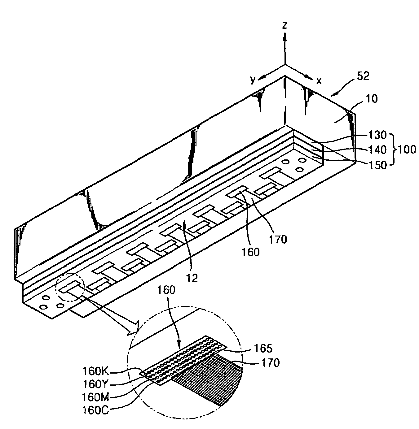
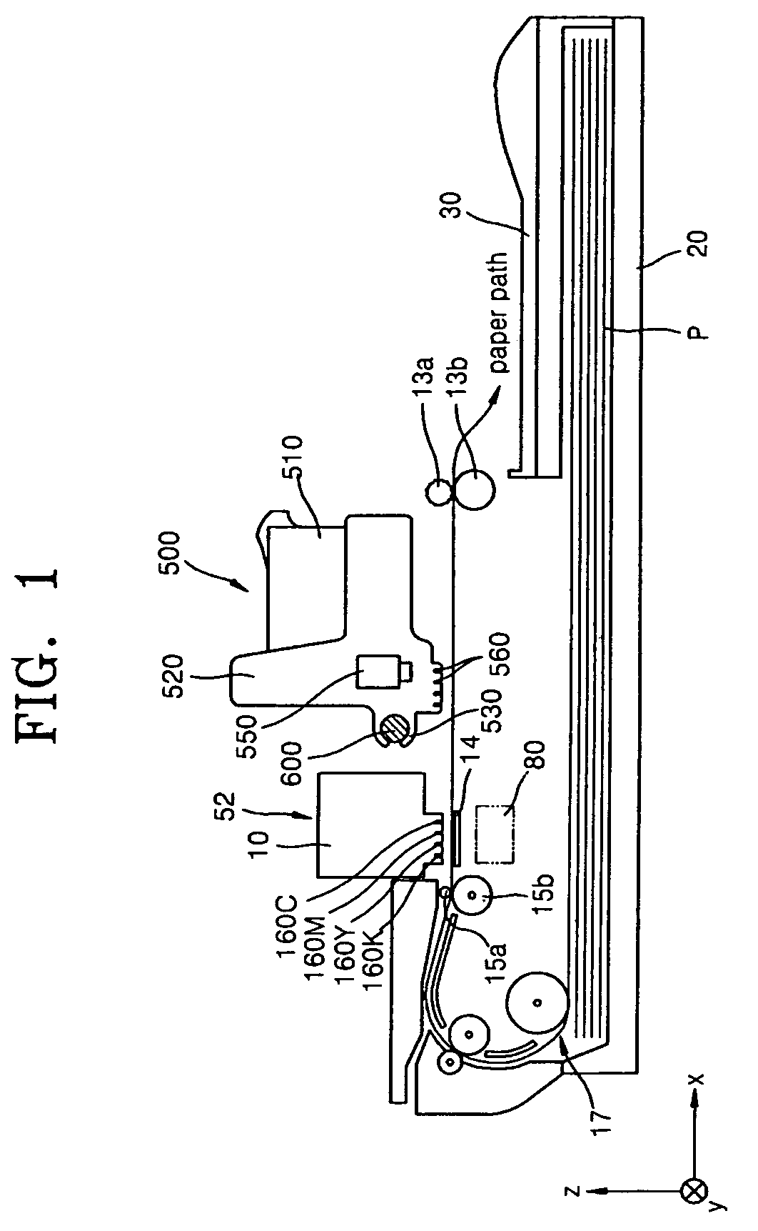
[0050]FIG. 1 is a side sectional view illustrating an inkjet image forming apparatus, according to an embodiment of the present general inventive concept. Referring to FIG. 1, the inkjet image forming apparatus includes an array type printhead 52, a cassette 20 to store printing media (P), a pick-up roller 17 to pick up the printing media (P) one by one, feed rollers 15a and 15b to feed the picked-up printing medium (P) to a nozzle unit 12 (see to FIG. 3), a platen 14 to guide the printing medium (P) fed by the feeding rollers 15a and 15b while keeping the printing medium (P) at a predetermined distance from the nozzle unit 12, ...


PUM


Abstract

An inkjet image forming apparatus includes a printhead including a nozzle array having a plurality of nozzles arranged in a main scanning direction, an auxiliary printhead having an auxiliary nozzle to fire ink to assist the nozzles to print the image and capable of reciprocating in the main scanning direction, and a detecting unit formed integrally with the auxiliary printhead, and a control method of the inkjet image forming apparatus includes firing ink onto an ink firing position between ink dots printed by two neighboring nozzles in a high-resolution mode, and/or firing ink onto an ink firing position where a missing dot caused by a defective nozzle exists in a compensation mode.

Description

CROSS-REFERENCE TO RELATED APPLICATIONS[0001]This application claims priority under 35 U.S.C. §119(a) from Korean Patent Application No. 10-2006-0000509, filed on Jan. 3, 2006, in the Korean Intellectual Property Office, the disclosure of which is incorporated herein in its entirety by reference.BACKGROUND OF THE INVENTION[0002]1. Field of the Invention[0003]The present general inventive concept relates to an inkjet image forming apparatus and a control method of the inkjet image forming apparatus, and more particularly, to an array type inkjet image forming apparatus having a plurality of nozzles arranged over a width direction of a printing medium for high-speed printing.[0004]2. Description of the Related Art[0005]Generally, an inkjet image forming apparatus prints an image on a printing medium by firing ink using an ink cartridge that is located a predetermined distance from a top surface of the printing medium and reciprocating in a perpendicular direction (hereinafter, referre...

Claims


Application Information

Patent Timeline
IPC IPC(8): B41J29/38
CPCB41J2/155B41J2/2139B41J2202/20B41J29/38B41J29/393B41J3/543A47L13/256A47L13/258
Inventor JUNG, YOUN-GUNPARK, HEON-SOO
Owner SAMSUNG ELECTRONICS CO LTD
Why Eureka
Try Eureka