
Imaging apparatus

Inactive Publication Date: 2007-07-05
SONY CORP
View PDF6 Cites 39 Cited by
  • Summary
  • Abstract
  • Description
  • Claims
  • Application Information

AI Technical Summary

Benefits of technology

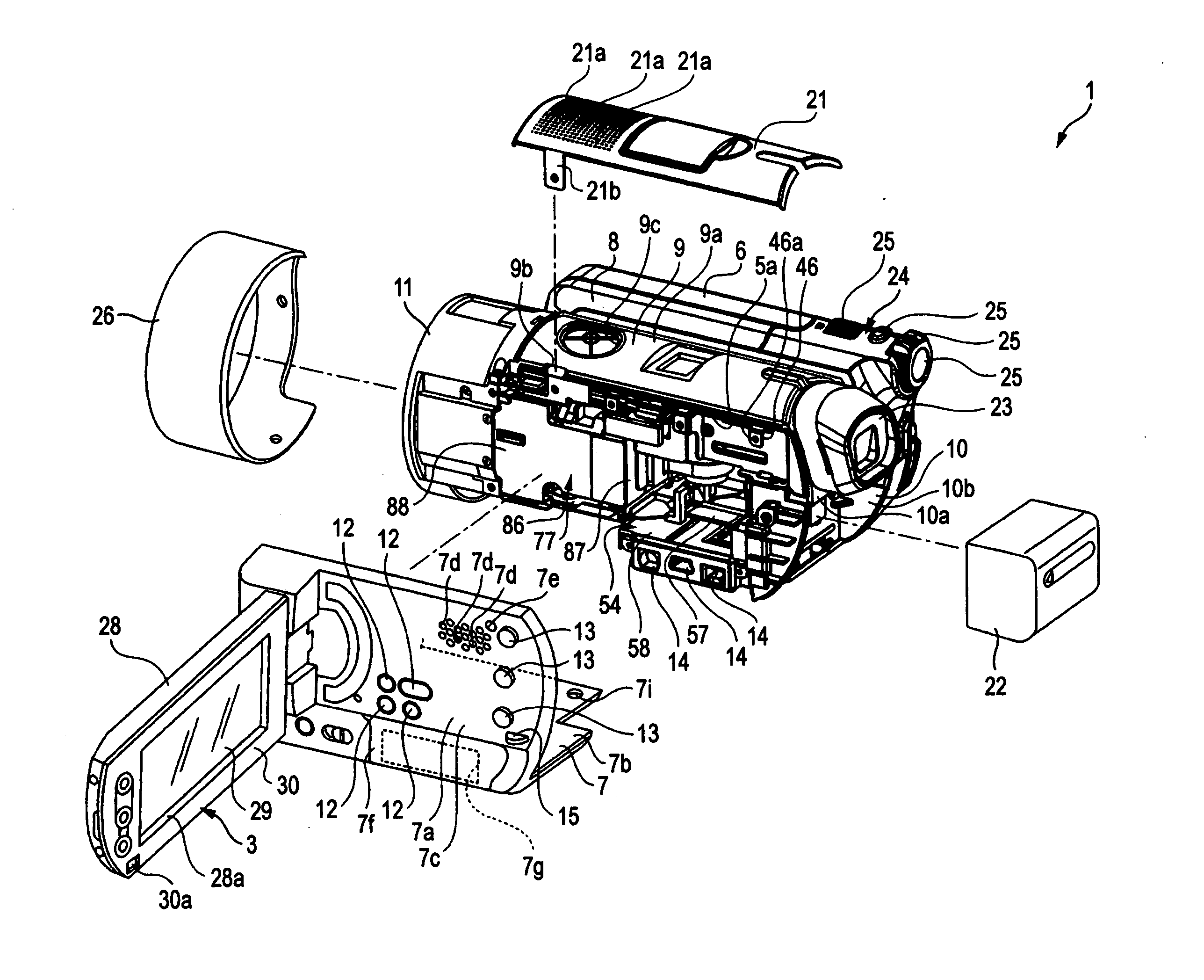
[0012] Therefore, vibration, heat and sound generated in one of the imaging block or the recording medium are less easily transmitted to the other of the recording medium or the imaging block. This makes it possible to improve reliability of operations of the imaging block and the recording medium.
[0013] According to another embodiment of the invention, the imaging apparatus further includes a control circuit board arranged in the imaging-block arranging section, the control circuit board including a driving circuit for driving the recording medium; a through hole formed in the partition wall; a wiring board connecting the control circuit board and the recording medium via the through hole; and a cover member that closes the through hole. Thus, a shielding property between the media housing section and the imaging-block arranging section is high. This makes it possible to improve a rate of control of transmission of vibration, heat, and sound between these sections.
[0014] According to still another embodiment of the invention, the wiring board is pressed against an opening edge of the through hole and held by the cover member. This makes it possible to prevent the wiring board from coming out of the control circuit board.

Problems solved by technology

Therefore, vibration, heat and sound generated in one of the imaging block or the recording medium are less easily transmitted to the other of the recording medium or the imaging block.

Method used


Image

  • Imaging apparatus
  • Imaging apparatus
  • Imaging apparatus

Examples


Embodiment Construction

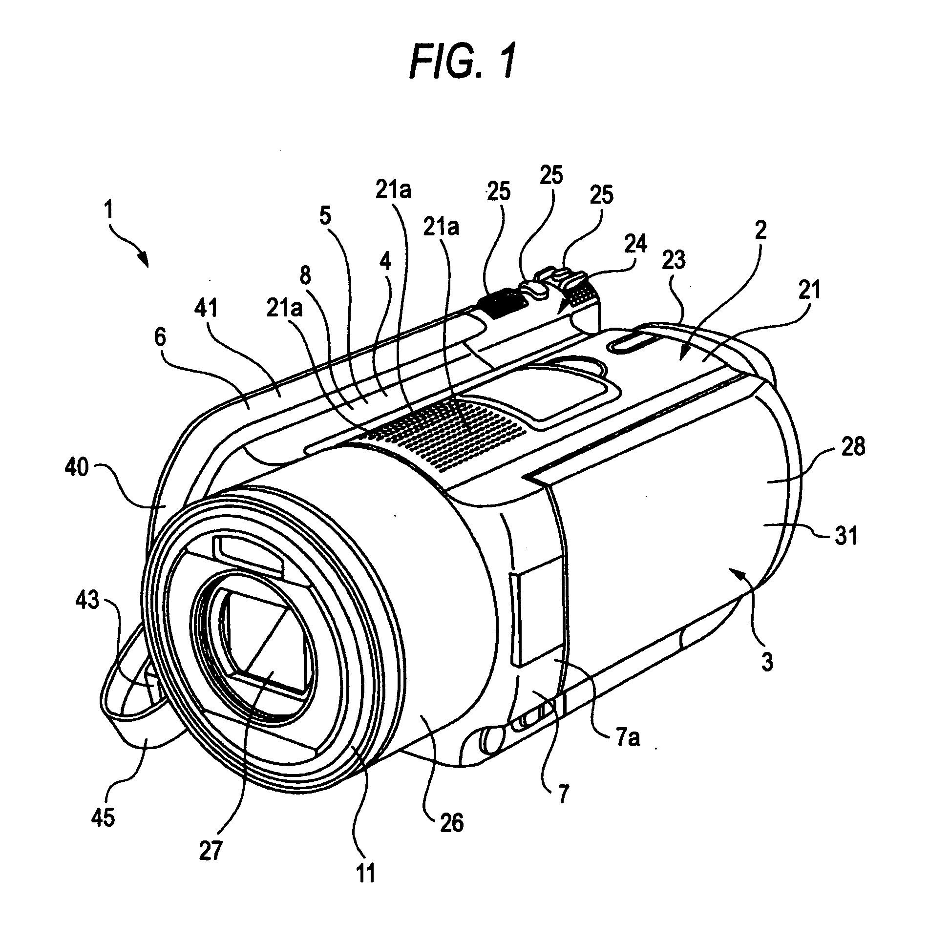
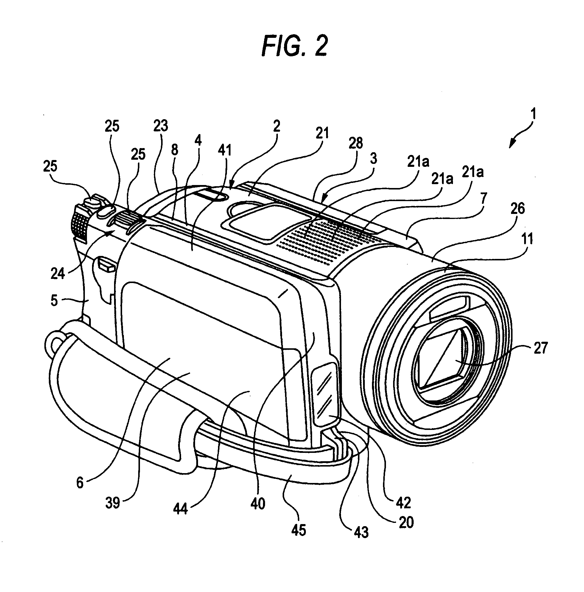
[0041] An imaging apparatus according to the embodiments of the invention will be hereinafter explained with reference to the accompanying drawings.

[0042] In the following explanation, an imaging apparatus according to an embodiment of the invention is applied to a video camera that can perform still image photographing and moving image photographing.

[0043] It is possible to apply the invention to various imaging apparatuses having functions of moving image photographing or still image photographing such as a camera built in a cellular phone or a computer and a still camera.

[0044] In the following explanation, respective directions of front and rear, up and down, and right and left are indicated as directions viewed from a photographer side. A subject side is referred to as the front and the photographer side is referred to as the rear.

[0045] An imaging apparatus (a video camera) 1 includes a body unit 2 and a display unit 3 that is supported on the body unit 2 to freely move ro...


PUM


Abstract

An imaging apparatus includes an outer housing; an imaging-block arranging section in the outer housing, the imaging-block arranging section including an imaging block having predetermined lenses and an imaging device; a media housing section in the outer housing, the media housing section being configured to house a recording medium for recording a photographed image. In the imaging apparatus, a partition wall partitions the imaging-block arranging section from the media housing section.

Description

CROSS-REFERENCE TO RELATED APPLICATIONS [0001] The present application claims priority from Japanese Patent Application No. JP 2005-360492 filed on Dec. 14, 2005, the disclosure of which is hereby incorporated by reference herein. BACKGROUND OF THE INVENTION [0002] 1. Field of the Invention [0003] The present invention relates to a technical field for imaging apparatuses. More specifically, the invention relates to a technical field for realizing, for example, prevention of transmission of heat and transmission of sound between an imaging block and a recording medium by providing a partition wall that partitions an imaging-block arranging section in which the imaging block is arranged and a media housing section that houses the recording medium. [0004] 2. Description of the Related Art [0005] There are imaging apparatuses that can perform moving image photographing and still image photographing such as a video camera and a still camera. [0006] In the imaging apparatuses, a photograp...

Claims


Application Information

Patent Timeline
IPC IPC(8): H04N5/225
CPCH04N5/2251H04N23/531G03B9/02G03B9/00H04N23/00
Inventor KAJIKAWA, KATSUHARUAMATATSU, SEIYA
Owner SONY CORP
Learn More