Method and apparatus for providing an LED light for use in hazardous locations

Active Publication Date: 2007-07-05
DIALIGHT CORP
View PDF10 Cites 35 Cited by
  • Summary
  • Abstract
  • Description
  • Claims
  • Application Information

AI Technical Summary

Problems solved by technology

There are many industrial environments where explosive atmospheres are present due to the nature of the products produced or processed.
Such sources while providing good photometric propertie

Method used


Image

  • Method and apparatus for providing an LED light for use in hazardous locations
  • Method and apparatus for providing an LED light for use in hazardous locations
  • Method and apparatus for providing an LED light for use in hazardous locations

Examples


Embodiment Construction

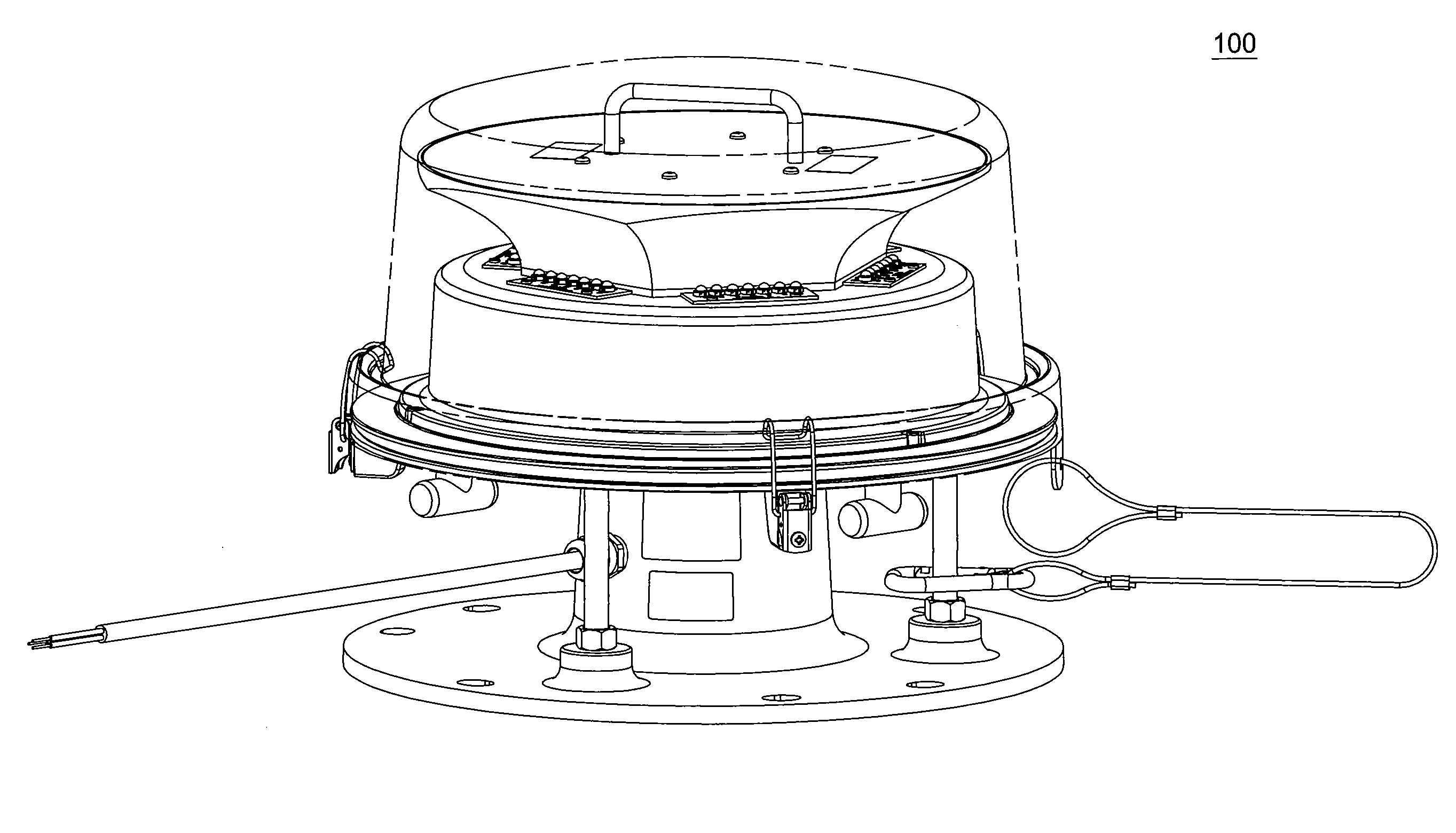
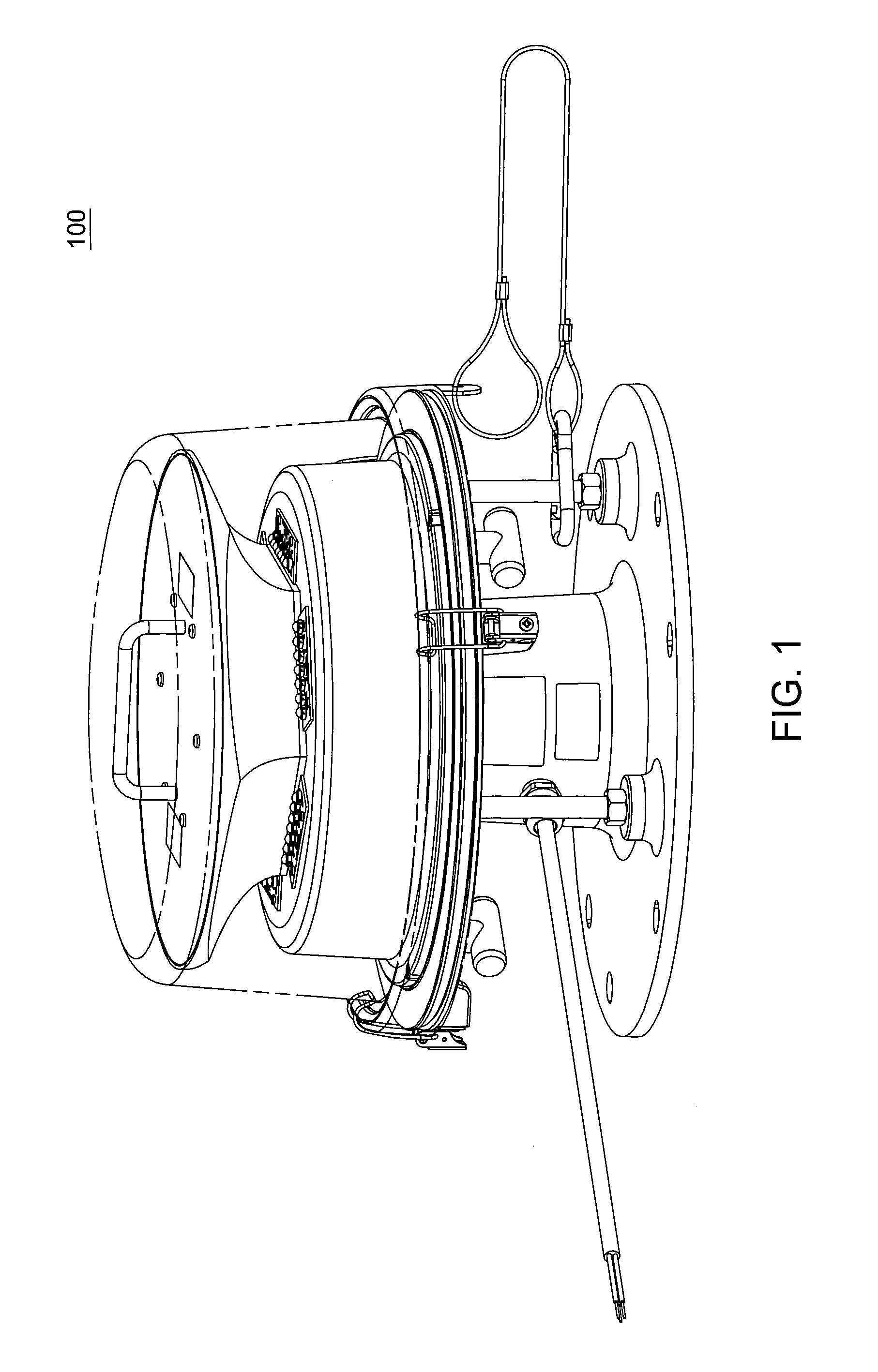
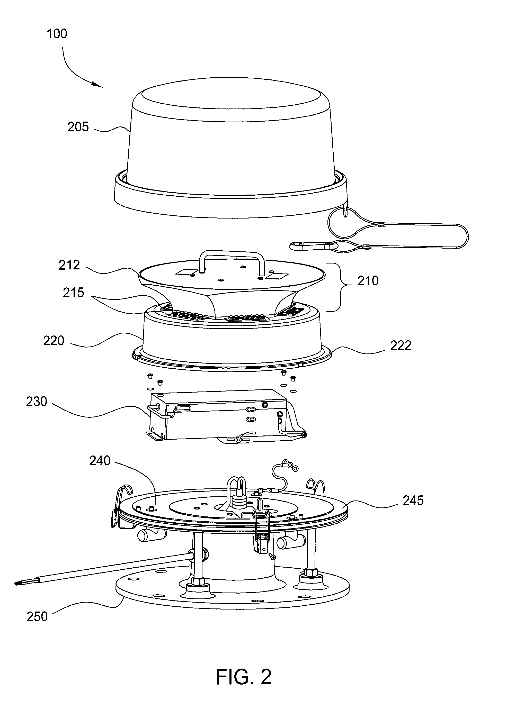
[0016]FIG. 1 illustrates an LED beacon warning light 100 (broadly a lighting source) related to the present invention. Such lights are used to signal obstructions to aviation such as radio towers, flare stacks, etc. More specifically, the LED beacon warning light 100 of the present invention is capable of being deployed in a hazardous environment. In one embodiment, a hazardous environment encompasses an environment that is hazardous due to the presence of flammable / combustible gases (e.g., acetylene, ethylene, propane and hydrogen), due to the presence of flammable / combustible dusts including conductive metal, carbonaceous dust and grain dust, and / or due to the presence of flammable / combustible fibers or flyings.

[0017] One unique difference of the LED beacon warning light 100 of the present invention when compared to a traditional beacon is that the typical traditional light source is replaced by one or more light emitting diodes (LEDs). In one embodiment, the LED beacon warning l...


PUM


Abstract

A lighting source that can be deployed in a hazardous environment is disclosed. For example, the lighting source comprises at least one light emitting diode and a power supply for providing power to the at least one light emitting diode. The lighting source also comprises an enclosure for housing the at least one light emitting diode and the power supply, where said lighting source is for deployment in a hazardous environment.

Description

[0001] This application claims the benefit of U.S. Provisional Application No. 60 / 748,090 filed on Dec. 6, 2005, which is herein incorporated by reference. [0002] The present invention relates generally to an LED light.BACKGROUND OF THE INVENTION [0003] There are many industrial environments where explosive atmospheres are present due to the nature of the products produced or processed. Facilities such as oil refineries, gas processing plants, mines, grain elevators, etc. are some examples of such environments where electrical discharges must be tightly controlled in order to prevent explosions. [0004] Over the years standards have been developed to insure electrical products which minimize the potential for electrical discharges such as sparks or arcs. Through a design process of careful component selection, proper pc board trace spacing, appropriate dielectric insulation, etc. products can be produced which can be safely used in these hazardous environments. [0005] In order to dev...

Claims


Application Information

Patent Timeline
IPC IPC(8): F21V33/00
CPCF21S10/06F21V21/30F21V23/04F21V25/12F21V31/04F21W2111/00F21W2111/06F21V29/76F21V29/89F21Y2105/10F21Y2115/10H05B45/345H05B45/355H05B45/385
Inventor CURRAN, JOHNPECK, JOHNBEBBORN, KEVINLEIB, WILLIAM
Owner DIALIGHT CORP
Why Eureka
Try Eureka