
Toner container and image forming apparatus

a technology of toner container and image forming apparatus, which is applied in the direction of electrographic process apparatus, instruments, optics, etc., can solve the problems of increasing the replacement frequency the inability to increase the toner amount and the inability to increase the height of toner storage containers

Active Publication Date: 2007-07-05
RICOH KK
View PDF47 Cites 75 Cited by
  • Summary
  • Abstract
  • Description
  • Claims
  • Application Information

AI Technical Summary

Benefits of technology

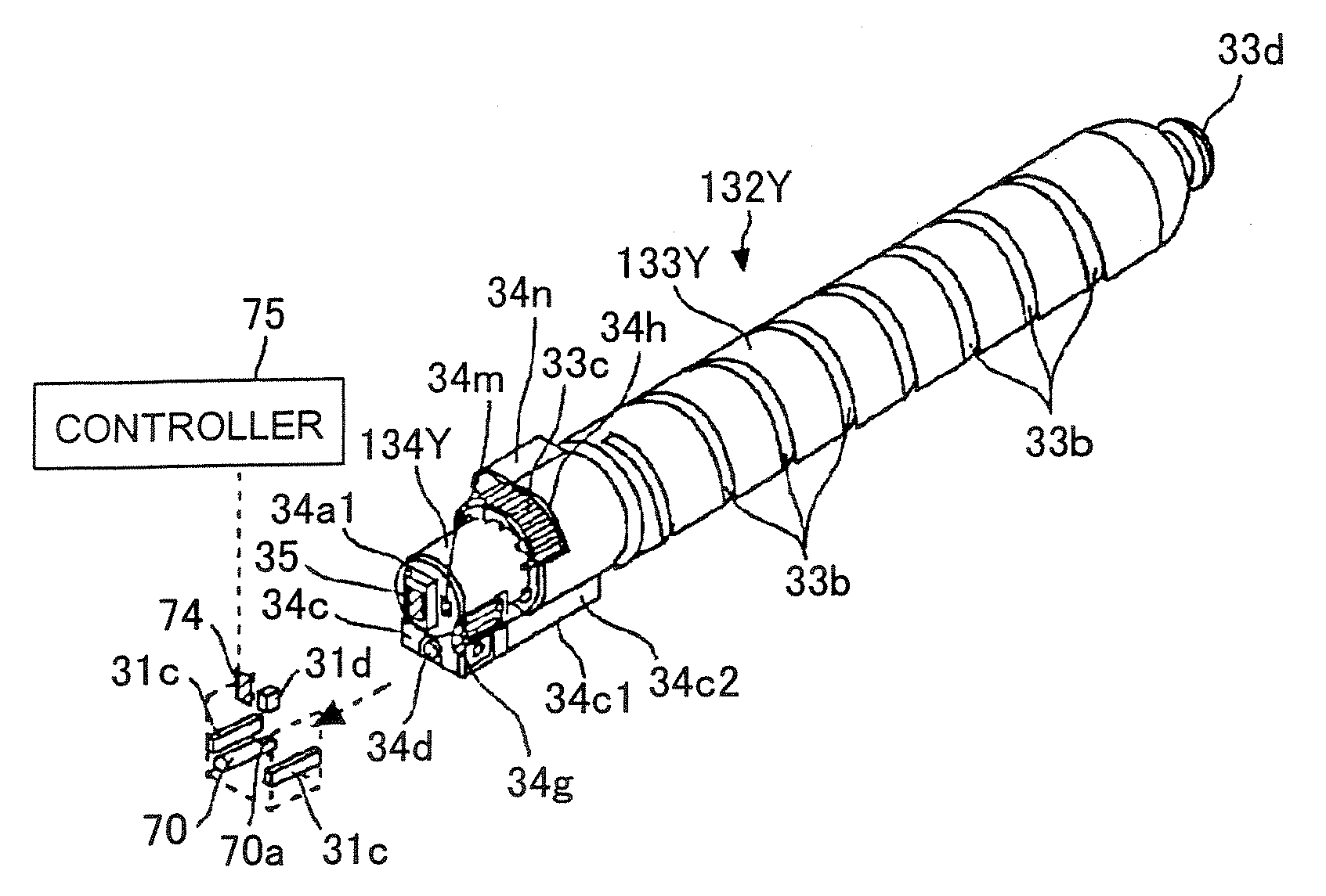
The present invention provides a solution for the problems in conventional technology by providing a toner container that can be easily attached and detached from an image forming apparatus. The toner container includes a longitudinal container body with a gear that engages with a drive gear in the main body of the apparatus. The container body has a held portion that is attached to the toner-container holder and includes a toner outlet for discharging the toner. The held portion is held by the toner-container holder in non-rotating manner and is biased downwardly by a force applied from the drive gear to the gear when the drive gear rotates. This allows for easy attachment and detachment of the toner container from the image forming apparatus.

Problems solved by technology

However, there is a disadvantage such that the toner amount of the toner storage container cannot be increased, which leads to an increase in the replacement frequency of the toner storage container.
Therefore, if the toner amount is desired to be increased, the height of the toner storage container is inevitably increased.
In other words, when the held portion is directed downward, the toner is deposited on the side of the held portion by its own weight, which may lead to toner aggregation.
If the toner container with the toner aggregated on the side of the held portion is set in the image forming apparatus, the toner is insufficiently discharged from the toner outlet, which also causes the toner not to be supplied sufficiently to the developing device.
Furthermore, if a toner lump is produced caused by the toner aggregation, this may cause a failure in toner conveyance or an abnormal image.
These problems quite often occur especially when the toner container with the held portion directed vertically downward is left standing for a long time or under high-temperature and high-humidity environments.
However, the toner containers in Patent document 1 or so are disadvantages in terms of operability / workability upon its attachment / detachment (replacement).
A first disadvantage is such that the attachment / detachment operation to / from the toner-container holder is implemented with a plurality of operations.
A second disadvantage is such that it is difficult for the user to check that the operation is performed properly nearly until the completion of the attachment operation.
More specifically, the user cannot feel certain that the operation is correct at the point in time when the operation of opening the main-body cover and the operation of placing the toner container on the toner-container holder are complete.
A third disadvantage is such that the upper side of the toner-container holder is restricted in terms of layout.
However, the toner storage container according to Patent document 3 or the like also has some disadvantages in terms of operability / workability upon its attachment / detachment.
A first disadvantage is such that the toner amount of the toner storage container cannot be increased and the frequency of replacement of the toner storage container therefore increases.
A second disadvantage is such that it is difficult for the user to feel certain that no erroneous operation is done.
More specifically, because the plug member opens / closes the toner outlet in synchronization with the open / close operation of the open / close holder, it is difficult for the user to feel if the toner outlet is actually opened or closed because the user does not touch the toner storage container during the operation.
The toner bottle described in Patent document 4 may sometimes has some advantages such that the operability / workability upon the replacement is improved as compared with that of Patent document 5, but also has some disadvantages such that toner may be leaked from a gap between the bottle body and the case after the time elapsed.
Such vibrations in the radial direction of the bottle body are repeated over time, the sealing capability of the seal member gradually deteriorates.
In other words, the opening is radially vibrated again and again, a deformed shape of the seal member having elasticity (shape to seal the gap) is not fixed, and the restoring force thereof deteriorates, which results in occurrence of a gap in the space which should be sealed.
If the toner is leaked to the outside of the toner bottle in this manner, the toner is wasted, and the inside of the image forming apparatus is contaminated with the toner.
In other words, to rotate such a toner bottle that the filling amount of toner is increased and the weight of the toner bottle is thereby increased, a large driving force is required.
Therefore, the amount of vibration in the radial direction of the opening increases associated with an increase in the torque, uneven rotation, vibration of the bottle body.
Furthermore, the operation time (life) of the toner bottle having the large capacity is increased according to the toner amount increased, which causes the time for which the vibration of the opening is affected on the seal member to be increased.
However, even if the seal member with elasticity is formed into the concave shape, this shape does not help control the radial vibration of the opening.
The effect of directly resolving the problems cannot thereby be expected.

Method used


Image

  • Toner container and image forming apparatus
  • Toner container and image forming apparatus
  • Toner container and image forming apparatus

Examples


eighteenth embodiment

[0544] Another feature of the invention which may be applied to any of the embodiments is explained below with reference to FIGS. 82-88. FIG. 82 is a schematic of toner containers filled with toners of colors such as yellow (Y), magenta (M), cyan (C), and black (K) respectively when viewed from the held portions 34 (Y, M, C, K) of the toner containers. As shown in FIG. 82, a convex portion (which corresponds to the convex portion 34n of the first embodiment) protruded from the side face of the held portion 34 is different from others in the position, the shape, and the number for each color container.

[0545] As shown in FIG. 82 which is to scale, the toner container 32K for black toner has one convex portion 34nk on the left side with respect to the held portion 34K. The convex portion 34nk is set so that the protrusion in the horizontal direction is slightly longer than that of the convex portions for the other colors at the same height. As a result, the toner container 32K is prev...


PUM


Abstract

A toner container includes a longitudinal container body and a held portion. The longitudinal container body has a first end and a second end distal to the first end in a length direction of the container body. The container body includes a gear configured to engage with a drive gear provided in the main body. The held portion is attached to the first end of the container body and configured to be detachably attached to the toner-container holder. The held portion includes a toner outlet, is configured to be held by the toner-container holder in non-rotating manner, and is biased downwardly by a force applied from the drive gear to the gear when the drive gear rotates.

Description

CROSS-REFERENCE TO RELATED APPLICATIONS [0001] This application claims the benefit of U.S. Provisional Application Ser. No. 60 / 850,675, filed Oct. 11, 2006 and entitled “Toner Container and Image Forming Device” which is incorporated herein by reference. [0002] The inventions in this application are related to the inventions disclosed in the following Japanese patent applications: 2005-129866 filed Apr. 27, 2005, 2005-179200 filed Jun. 20, 2005, 2005-180082 filed Jun. 21, 2005, 2005-180153 filed Jun. 21, 2005, 2005-181371 filed Jun. 22, 2005, 2005-191090 filed Jun. 30, 2005, 2005-198355 filed Jul. 7, 2005, 2005-223438 filed Aug. 1, 2005, 2005-302636 filed Oct. 18, 2005, 2005-311112 filed Oct. 26, 2005, 2005-311787 filed Oct. 26, 2005, 2005-315311 filed Oct. 28, 2005, 2005-346038 filed Nov. 30, 2005, 2006-021362 filed Jan. 30, 2006, 2006-026258 filed Feb. 2, 2006, and 2006-029859 filed Feb. 7, 2006, and PCT patent application PCT / JP2006 / 308820 filed Apr. 27, 2006, each of which is in...

Claims


Application Information

Patent Timeline
Patent Type & Authority Applications(United States)
IPC IPC(8): G03G15/08
CPCG03G2215/0668G03G2215/0695G03G15/0886G03G15/0872G03G15/0879G03G15/0863G03G15/08
Inventor TAGUCHI, NOBUYUKIYAMANE, MASAYUKIYOSHIZAWA, HIDEOKURENUMA, TAKEROHTAMAKI, TAKAYUKITERAZAWA, SEIJIHASEGAWA, MASASHISATOH, FUMIEHITOSUGI, TERUOHISAZUMI, TAKASHIKATSUYAMA, GORO
Owner RICOH KK
Learn More