Riparian flood wall structure

a flood wall and riparian technology, applied in the direction of buttress dams, artificial islands, excavations, etc., can solve the problems of limiting the utility of emergency situations, difficult process, and inability to easily adapt the size of the formed dam to accommodate different sized areas

Active Publication Date: 2007-07-05
VERDEN CRAIG A
View PDF25 Cites 32 Cited by
  • Summary
  • Abstract
  • Description
  • Claims
  • Application Information

AI Technical Summary

Benefits of technology

[0008] The present invention comprises interlocking, stacking blocks having a hollow interior that can be easily filled with water so that the wall will have added strength and stability when holding back flood waters. Ideally, this modular flood wall structure will be used in place of sandbags that are commonly used to prevent flooding in those certain areas.
[0011] Alternatively, the assembled wall may also include blocks that are not composed of cubical or parallelepiped shaped blocks. Such an arrangement of blocks may be advantageous for constructing a wall on a sloped surface.

Problems solved by technology

However, this can be an arduous and difficult process.
While these bladder-type walls do form a barrier to keep water away, the size of the formed dam cannot be easily adapted to accommodate different sized areas.
Thus, if the area that needs to be dammed is larger than expected, it is not easy to stack such structures upon one another, thereby limiting their utility in emergencies.
Similarly, such structures are generally space intensive, which is inhibitive for use by individuals.
However, the blocks are not interconnectable horizontally, or side to side, which limits the efficiency of using the blocks for areas that do not correlate directly to the size of the blocks.
If the length of the wall needs to be extended, the wall will not easily form a complete sealing structure.
Still, the modular blocks are not designed so that they can be stacked in an upwardly interlocking fashion, which limits the height of the wall.
If it was necessary to stack the blocks upon one another, they would not necessarily form a tight seal, and it may be difficult to fill lower level blocks with material.
However, the discussed blocks are not lightweight, which does not make the wall as useful as necessary in emergency situations.
The system is not designed as a lightweight portable structure that may be easily erected in emergency situations.

Method used


Image

  • Riparian flood wall structure
  • Riparian flood wall structure
  • Riparian flood wall structure

Examples


Embodiment Construction

[0033] Although the disclosure hereof is detailed and exact to enable those skilled in the art to practice the invention, the physical embodiments herein disclosed merely exemplify the invention which may be embodied in other specific structures. While the preferred embodiment has been described, the details may be changed without departing from the invention, which is defined by the claims.

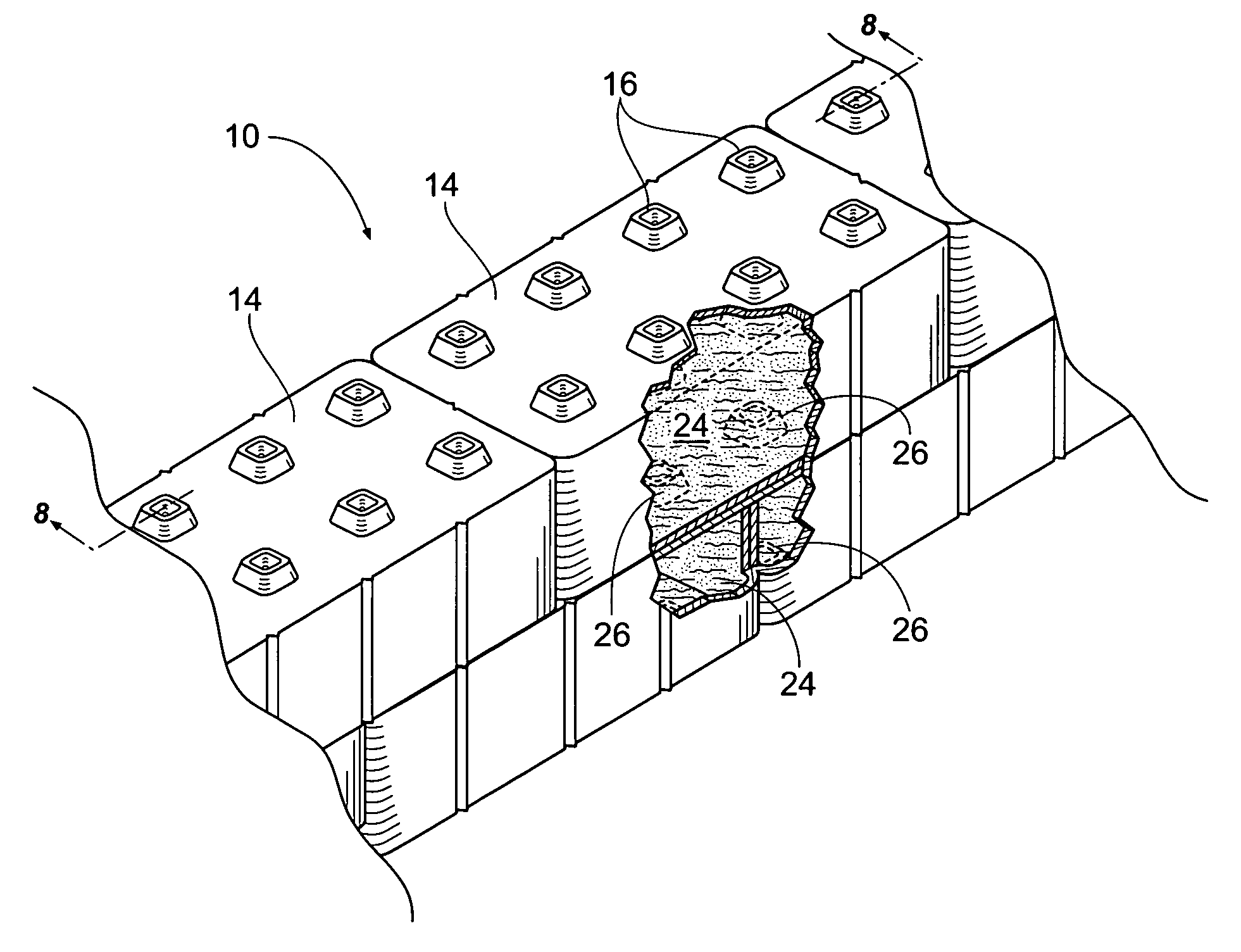
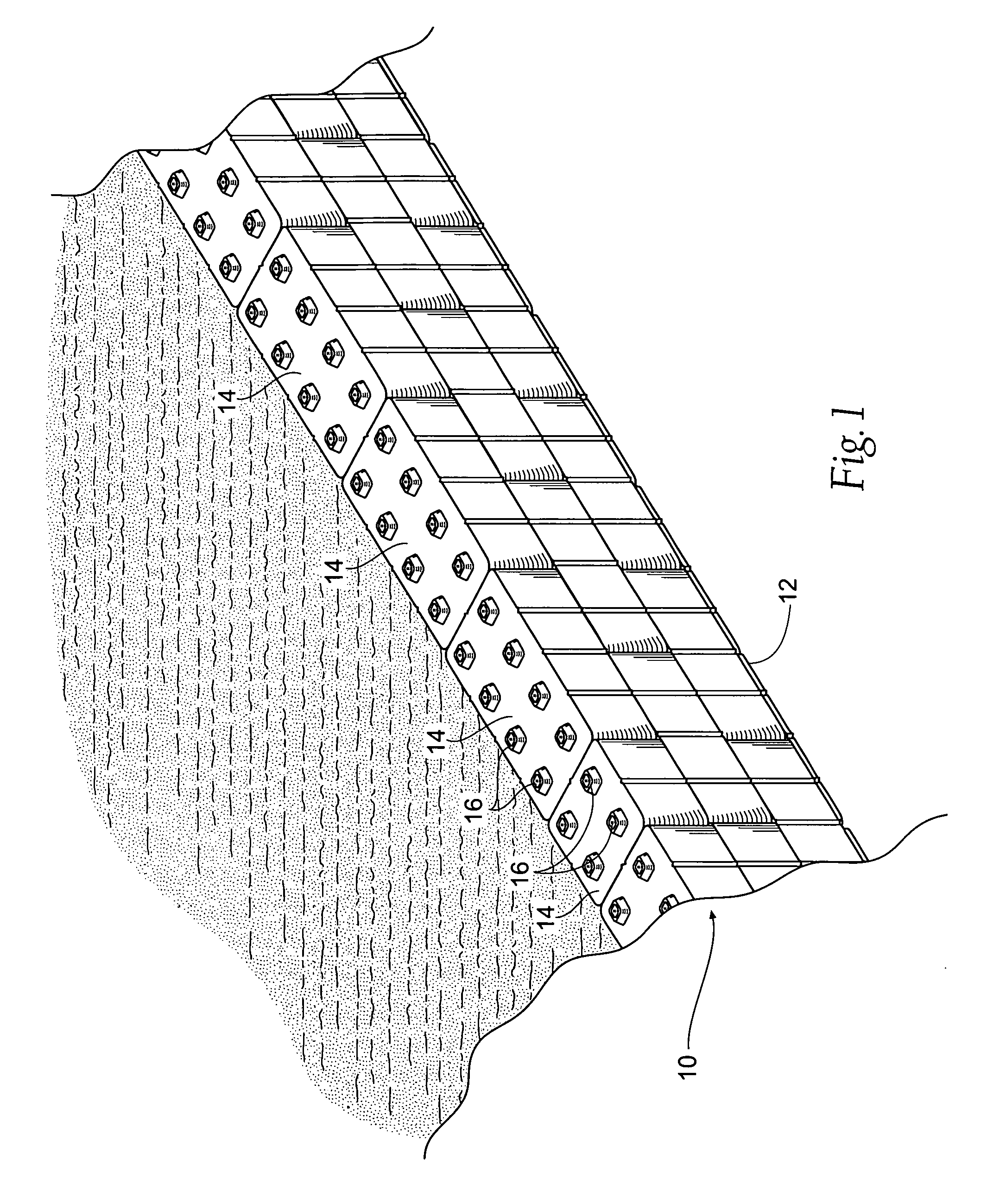
[0034]FIG. 1 shows a perspective view of a modular wall assembly 10. The assembly generally comprises a base member 12 and a plurality of stackable blocks 14. Each of the blocks 14 has a plurality of protuberances 16. The protuberances 16 are arranged so that the blocks 14 can be easily mated with one another in an interlocking fashion to form a solid wall. As shown, the blocks 14 can be of differing sizes from one another. The base member 12 preferably is secured to the ground or other external force with stakes, rods, or other possible securing devices (not shown).

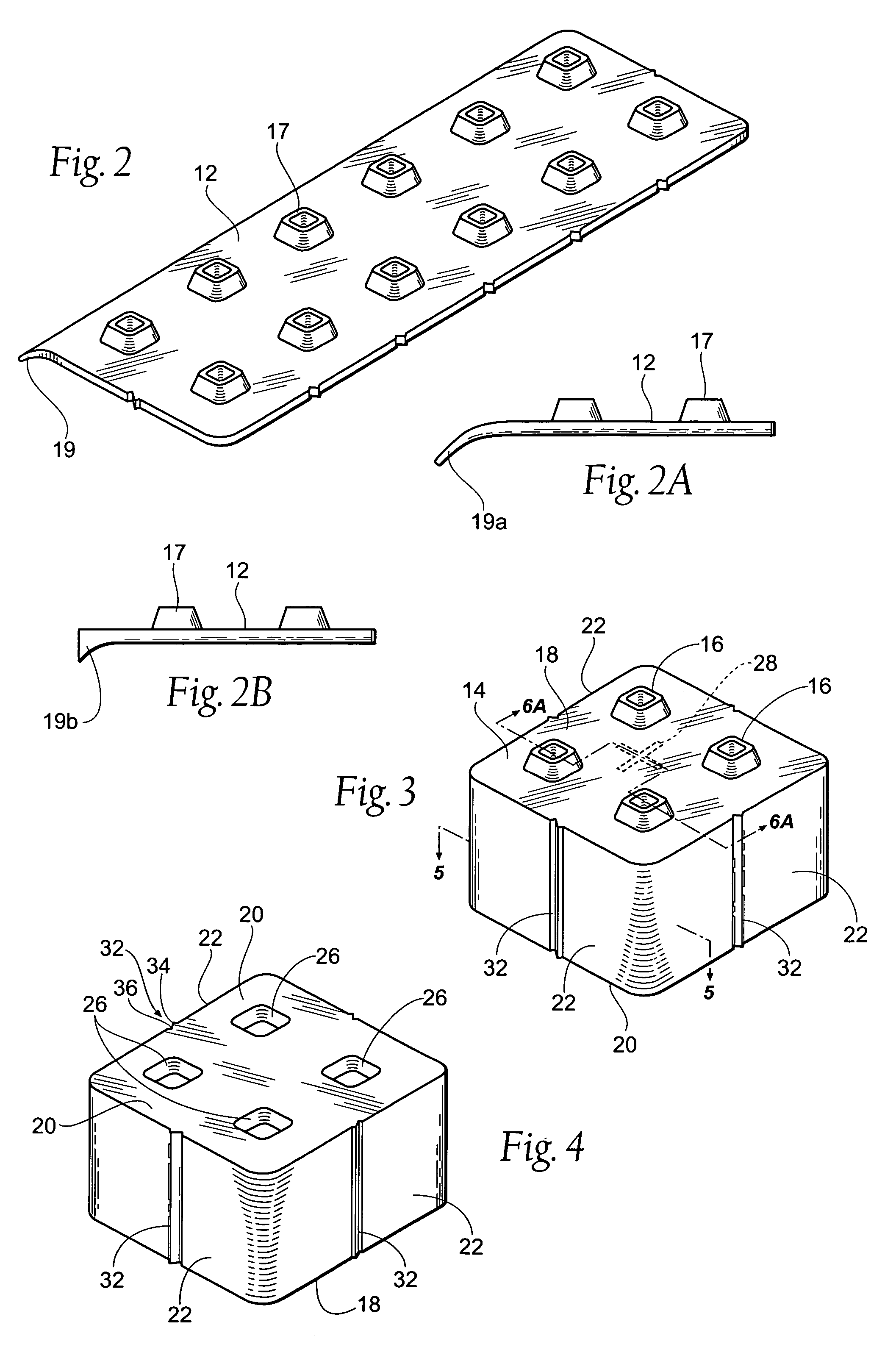
[0035] As shown in FIGS. 2, ...


PUM


Abstract

A modular flood wall assembly having a relatively flat base member having a plurality of ribs extending therefrom. The assembly further comprises a plurality of interconnectable blocks, with each block having a top surface with at least one hollow protuberance, at least one side wall, a hollow interior, and a bottom surface having at least one hollow cavity. The cavities on the bottom surface of the blocks are matable with the ribs on the base member. The protuberances on the top surface of the blocks are matable with the receptacles on the bottom surface of a corresponding block.

Description

BACKGROUND OF THE INVENTION [0001] The present invention relates to mobile support structures and, more specifically, to mobile support structures to be used as break walls and flood walls. [0002] During floods, storms and bad weather, it may be necessary to quickly construct and erect levees, dams or the like along river banks and other water sources to protect against flood damage. Similarly, during particularly rainy seasons or heavy spring thaws it may be necessary to construct a temporary flood wall or dam until the water levels subside. Conventionally, this has been done by stacking sand bags upon one another to form a wall or barrier. However, this can be an arduous and difficult process. Thus, artificial walls have been designed that are easier to assemble and construct. [0003] Some contemplated structures have included inflatable walls. While these bladder-type walls do form a barrier to keep water away, the size of the formed dam cannot be easily adapted to accommodate dif...

Claims


Application Information

Patent Timeline
Patent Type & Authority Applications(United States)
IPC IPC(8): E02B7/14
CPCE02B3/108
Inventor STAUFFACHER, DEBORAH A.VERDEN, CRAIG A.
Owner VERDEN CRAIG A
Why Eureka
Try Eureka