Sterization container

a technology of sterilization container and container body, which is applied in the direction of disinfection, chemical/physical/physicochemical processes, chemistry apparatus and processes, etc., can solve the problems of unable to reliably prevent premature closing, possible implosion, and risk of premature closing

Inactive Publication Date: 2007-07-05
WAGNER GMBH FAB FUR MEDIZINISCHE GERATE
View PDF2 Cites 2 Cited by
  • Summary
  • Abstract
  • Description
  • Claims
  • Application Information

AI Technical Summary

Benefits of technology

[0018] The valve arrangement according to the invention may be arranged at any location in the sterilization container, i.e. in the lid or on the side walls of the trough. However, the valve is preferably arranged at the lowest point at the bottom of the trough in such a way that, during the sterilization operation, during which the vacuum valve is open, the condensate water can thus flow ...

Problems solved by technology

In the valve arrangement, however, the valve body must be reliably prevented from being pressed onto the valve seat prematurely by the inflowing steam, since otherwise no reliable sterilization could take place and the container could even possibly implode.
It has been found that the spring preloading of the valve body in the open position cannot reliably prevent premature closing in particular when this valve body subjected to the pressure of the flow medium has a considerable surface extent.
The risk of premature closing is there, depending on the load, due to the high inflow velocities.
The greater the amount of material to be sterilized which is in the container, the greater is the steam consumption required in the same time.
Accordingly, the container must be “resupplied” with steam, but this steam immed...

Method used


Image

  • Sterization container
  • Sterization container
  • Sterization container

Examples


Embodiment Construction

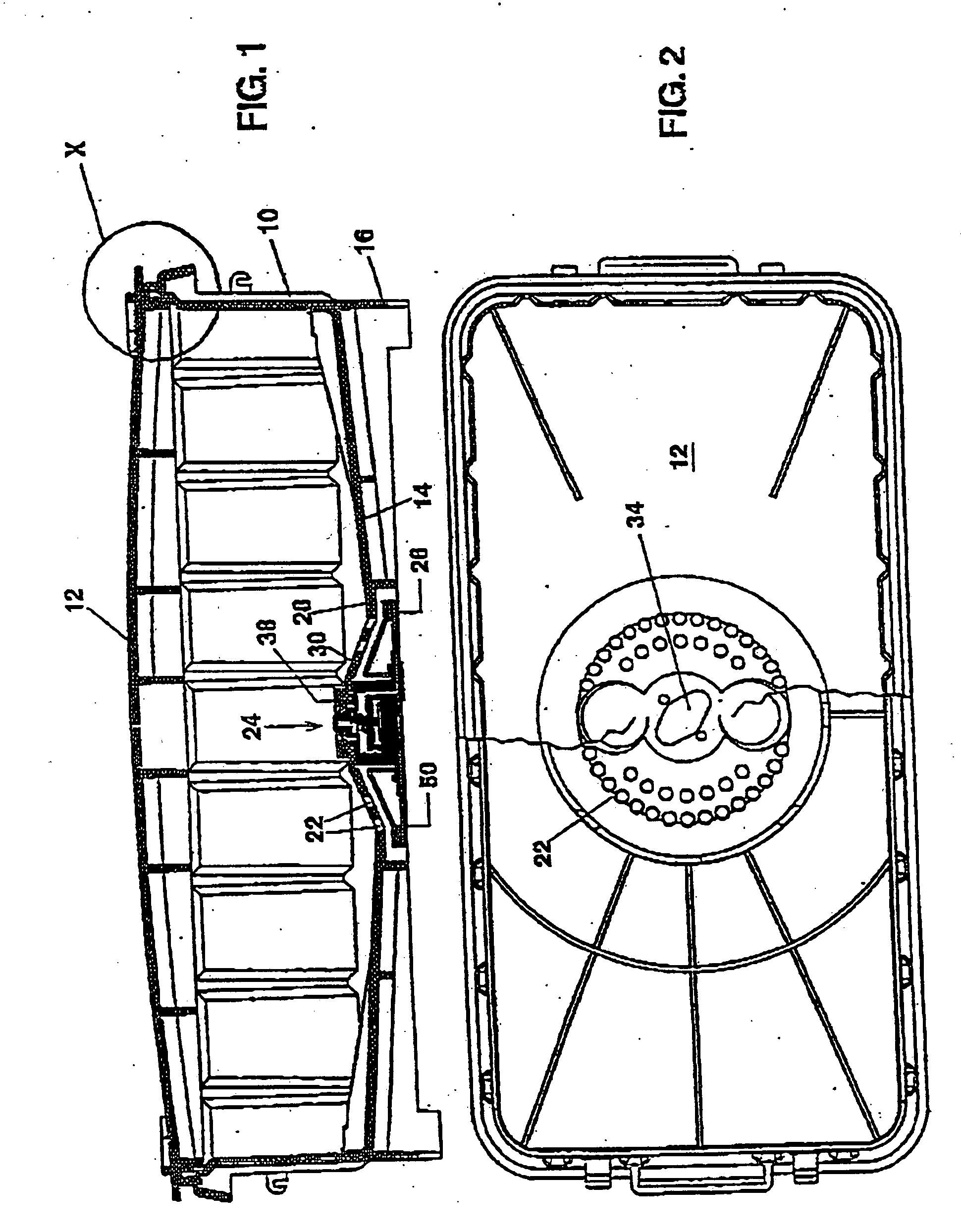
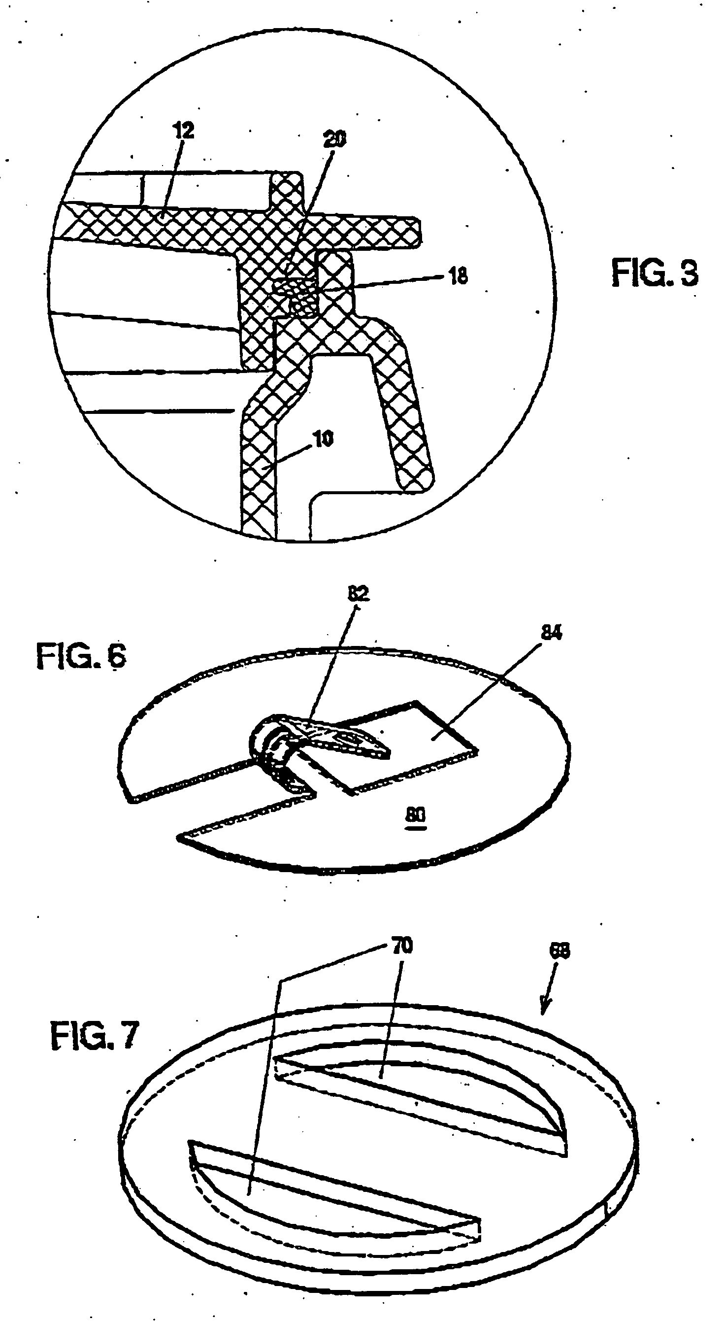
[0035] Referring to FIG. 1, the sterilization container consists of the trough 10 and the lid 12. The trough has a sloping bottom 14 and an encircling base frame 16. A sealing ring 18 of L-shaped cross section is arranged between the top rim of the trough 10 and the lid 12 (FIG. 3). This sealing ring, with its inwardly pointing leg, is captively inserted into an encircling groove 20 of the lid 12 and effects a seal downward and outward. The sealing ring 18 accordingly has positive locking in the horizontal, so that adhesive bonding need not be effected, but rather the seal can be exchanged on the spot without any effort. Even if the seal “sticks” slightly to the trough after prolonged mounting, the positive locking enables the lid to be removed without the seal being released from the latter. The seal has a double sealing seat: end-face contact on the one hand (especially at first—when the container is not under vacuum but is only closed with the fasteners), but, when the pressure f...


PUM


Abstract

A sterilization container has a valve arrangement that remains open in a venting phase and is then closed before a pressure difference is compensated for at a predetermined differential pressure. The valve remains closed until the container is opened for the purpose of withdrawing and using the sterilized instruments contained therein. The valve is actuated through a snap disk arrangement, the snap disks of which vault gradually into opposite directions at predetermined temperatures, thereby effecting a defined valve control. The snap disk arrangement is provided in a thermally isolated housing, which prevents a premature back-switching of certain snap disks that could be caused by a cooling-off as a result of the evaporation of condensate.

Description

CROSS-REFERENCE TO RELATED APPLICATION [0001] This application is a division of U.S. patent application Ser. No. 09 / 937,516, filed Mar. 6, 2002, which is a United States National Phase Application of PCT / EP00 / 02502, filed 21 Mar. 2000, which claims priority of German Application No. 199 13 417.0, filed 25 Mar. 1999. The PCT International Application was published in the German language.BACKGROUND OF THE INVENTION [0002] The invention relates to a sterilization container having a valve arrangement which permits a media exchange inside a sterilizer right into the vacuum drying phase and closes in the last ventilation phase, so that the vacuum prevailing at this instant in the container interior is maintained and the container remains hermetically sealed, the valve arrangement having a valve body subjected to the flow pressure. [0003] Such sterilization containers, as described, for example, in DE 41 11 075 C2, have the advantage that the material to be sterilized can be kept in the co...

Claims


Application Information

Patent Timeline
IPC IPC(8): A61L2/07A61L2/26
CPCA61L2/07A61L2/28A61L2202/122A61L2202/24A61L2202/121A61L2202/14
Inventor WAGNER, PETER
Owner WAGNER GMBH FAB FUR MEDIZINISCHE GERATE
Why Eureka
Try Eureka