
Power output device with fuel cell and method therefor

a technology of power output device and fuel cell, which is applied in the direction of battery/fuel cell control arrangement, secondary cell servicing/maintenance, electrochemical generator, etc., can solve the problems of limited actual output, unavailability of required output, and operator's sense of discomfort when the device is operated, etc., and achieves the effect of easy comparison

Inactive Publication Date: 2007-07-05
TOYOTA JIDOSHA KK
View PDF7 Cites 12 Cited by
  • Summary
  • Abstract
  • Description
  • Claims
  • Application Information

AI Technical Summary

Benefits of technology

[0039] If a maximum output of a fuel cell is derived from a current output of the fuel cell which is being operated, a state of power shortage is frequently detected because of rapid fluctuation of the load, and then the power shortage is frequently notified. On the contrary, the state of power shortage is determined based on the stable maximum output according to the power output device of the fifth aspect of the present invention so that the state of power shortage is notified only if an output of the fuel cell is lowered by a failure. Therefore, an operator can accurately be notified of the failure of the fuel cell without an influence of the load fluctuation.
[0072] The method of outputting power of the fifteenth aspect of the present invention has similar effects and actions to those of the power output device according to the sixth aspect of the present invention. Therefore, an operator can be notified of a failure of the fuel cell without an influence of the load fluctuation.

Problems solved by technology

However, with the above-mentioned art, a sense of discomfort may be given to an operator when the device is operated.
When the required output from the operator is larger than the possible output of the fuel cell, the actual output is limited to the possible output of the fuel cell.
Therefore, the operator has to conclude, from experience, that the required output is not available, whether by a failure in the power output device or the fuel cell not reaching normal operating conditions.
However, if the operator does not periodically use the power output device, it is difficult to come to an appropriate conclusion.

Method used


Image

  • Power output device with fuel cell and method therefor
  • Power output device with fuel cell and method therefor
  • Power output device with fuel cell and method therefor

Examples


Embodiment Construction

[0102] The following explains each preferred embodiment of the present invention according to a preferred embodiment applied to a vehicle and the following items. [0103] The First Preferred Embodiment [0104] A. Device Configuration: [0105] B. Electric Power Control Processes: [0106] C. Control Processes of the Output Limitation Warning Lamp: [0107] D. Effects: [0108] The Second Preferred Embodiment [0109] E. Device Configuration: [0110] F. Meter Control Processes: [0111] G Effects:

The First Preferred Embodiment

A. Device Configuration:

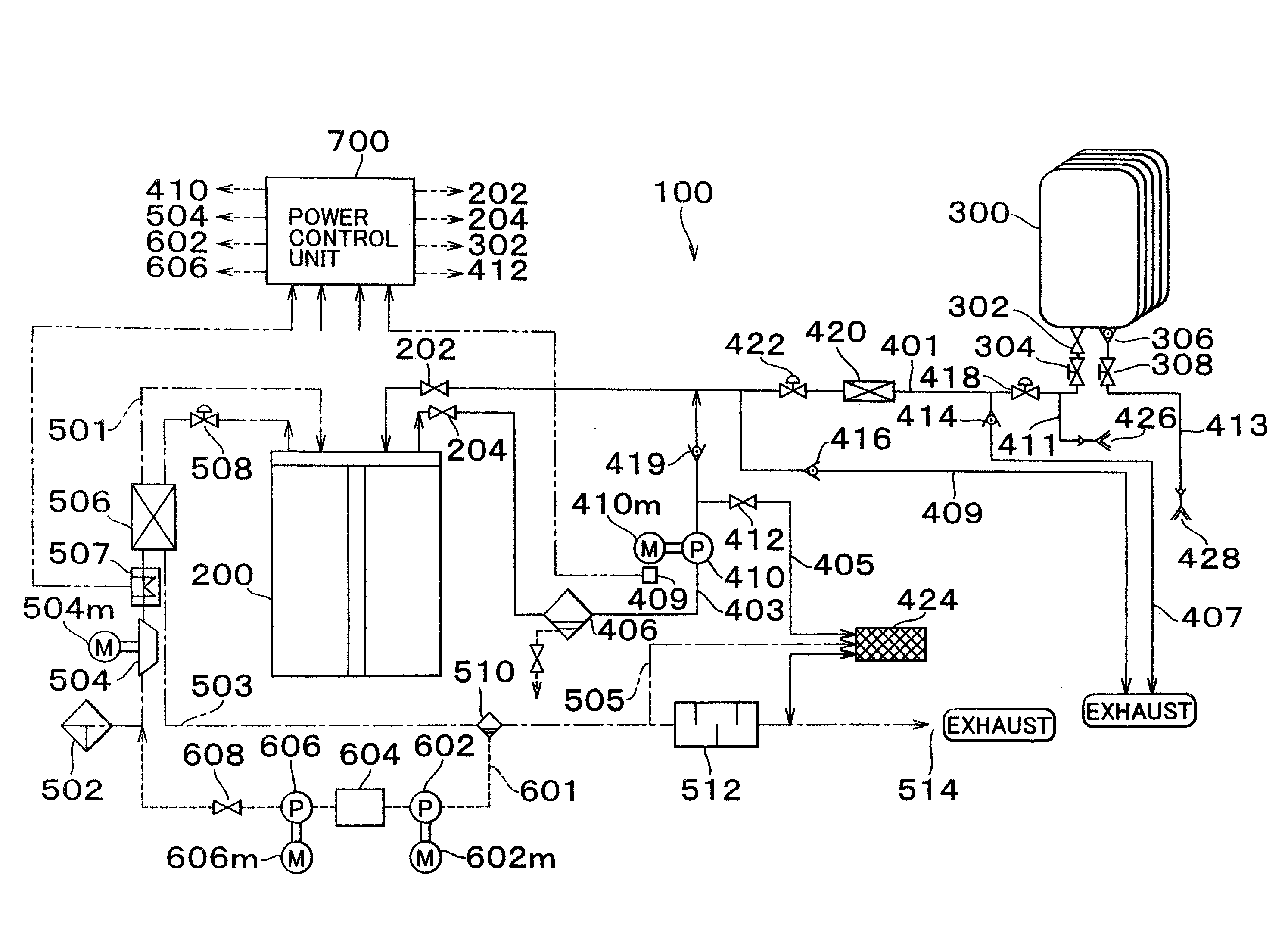
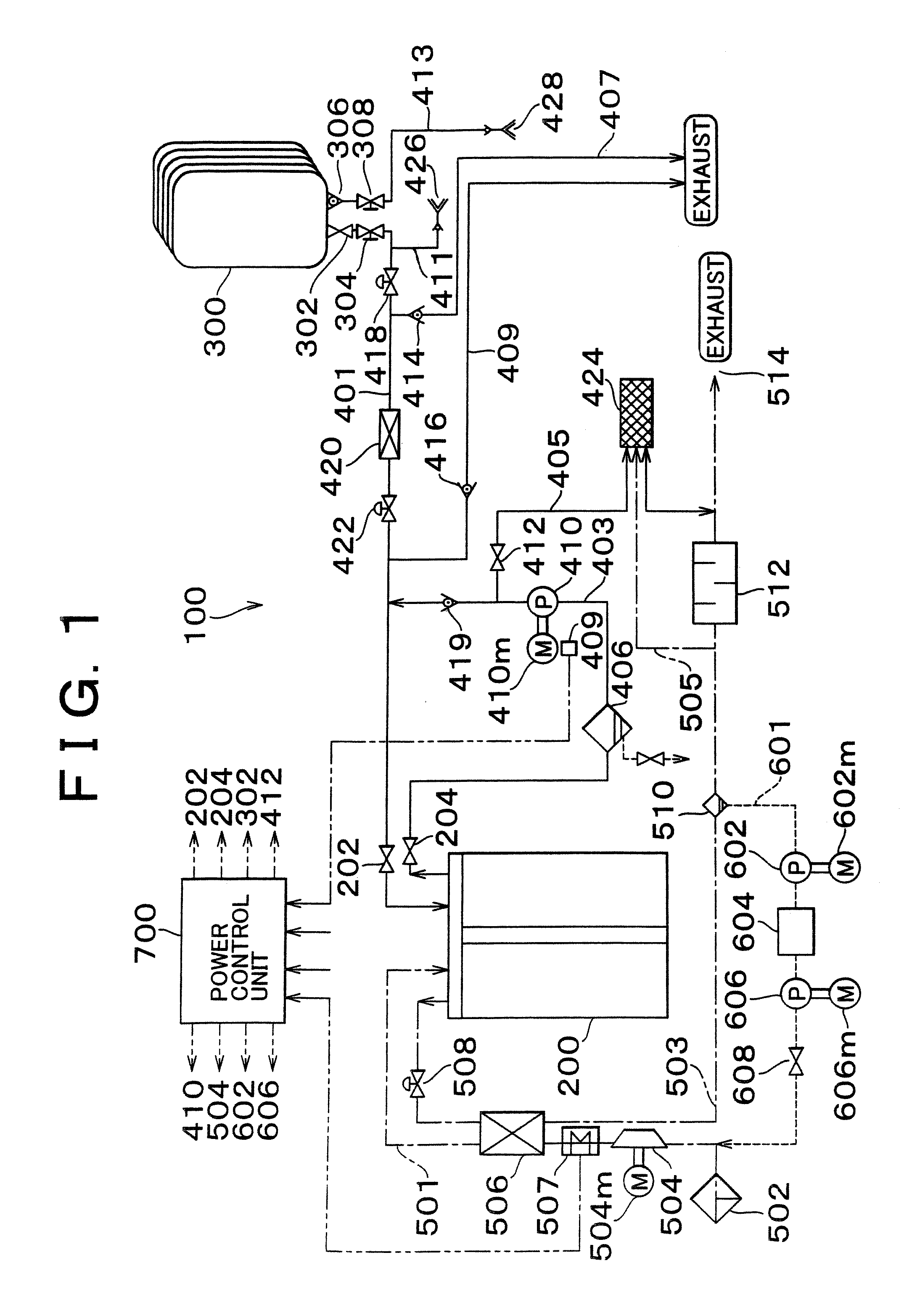
[0112]FIG. 1 is a block diagram mainly showing a gas system of a power output device for mounting on a vehicle as the first preferred embodiment of the present invention. A power output device for mounting on a vehicle 100 such as a car, according to the present preferred embodiment, mainly includes a fuel cell 200 supplied with hydrogen gas to generate electric power, a high-pressure hydrogen gas tank 300 for supplying hydrogen gas to the fuel cell...


PUM


Abstract

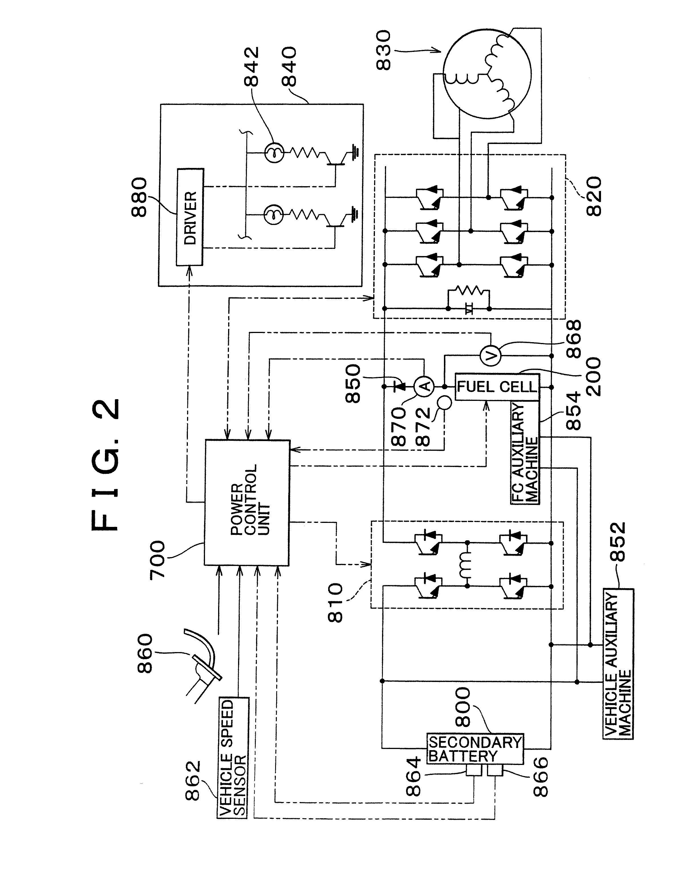
An output limitation warning lamp is turned on when a possible output Qf of the fuel cell is less than a predetermined value L2. The output limitation warning lamp is provided at a combination meter in an instrument panel. The output limitation warning lamp is also turned on when a possible output Qb of the secondary battery is less than a predetermined value L3. Furthermore, the output limitation warning lamp is also turned on when an allowable drive output Qh, which is the sum of the possible output Qf of the fuel cell and the possible output Qb of the secondary battery, has been less than a required output Ed* calculated at a step before carrying out output limitation to more than a certain extent for longer than a predetermined length of time.

Description

CROSS REFERENCE TO RELATED APPLICATION [0001] This application is a division of and claims the benefit of priority from U.S. Ser. No. 10 / 171,974, filed Jun. 17, 2002, and is based upon and claims the benefit of priority from the prior Japanese Patent Application Nos. 2001-181693, filed on Jun. 15, 2001 and 2002-25507, filed on Feb. 1, 2002, the entire contents of which are incorporated herein by reference.BACKGROUND OF THE INVENTION [0002] 1. Field of the invention [0003] This invention relates to a power output device with a fuel cell and a method of outputting power. [0004] 2. Description of Related Art [0005] A device, which is mounted on a vehicle and limits an actual output of a fuel cell according to a required output calculated from a position of an accelerator pedal, has been suggested (for example, Japanese Patent Laid-Open Publication No. 7-75214). The device alters operating conditions of the fuel cell according to the required output, and performs a control to secure tha...

Claims


Application Information

Patent Timeline
IPC IPC(8): H01M8/04H01M8/00B60L11/18
CPCB60L11/1887Y02T90/34B60L11/1894B60L2260/162H01M8/04365H01M8/04373H01M8/04589H01M8/04619H01M8/04626H01M8/04753H01M8/04776H01M8/0494H01M8/04947H01M8/04992H01M16/006Y02E60/50B60L11/1892B60L58/33B60L58/34B60L58/40Y02E60/10Y02T10/70Y02T90/40
Inventor FUJITA, TATSUYANIIMI, YASUHIKOKOTOH, TAKASHIMIZUNO, HIDEAKIWATANABE, NOBUOMATSUMOTO, TADAICHI
Owner TOYOTA JIDOSHA KK
Learn More