Supercharge Your Innovation With Domain-Expert AI Agents!

Battery device and electronic apparatus

a battery device and electronic equipment technology, applied in the field of battery devices and electronic equipment, can solve the problems of increasing the size of the battery device or the electronic equipment, miniaturizing the battery device and the electronic equipment, and improving the operability of the battery device, so as to enhance the usability of the electronic equipment

Active Publication Date: 2007-07-05
SONY CORP
View PDF5 Cites 17 Cited by
  • Summary
  • Abstract
  • Description
  • Claims
  • Application Information

AI Technical Summary

Benefits of technology

The present invention relates to a battery apparatus and electronic equipment with a battery attachment section. The battery apparatus includes a case, battery cell, and battery-side terminal, and the battery-side terminal has an identification section with an identification recess. The identification recess has a unique position, shape, and length that identifies the battery apparatus. The battery attachment section of the electronic equipment has an attachment terminal that connects to the battery-side terminal. The battery apparatus can be attached to the battery attachment section of the electronic equipment by sliding the case along its length direction. The battery apparatus can be easily identified and attached to the electronic equipment with the unique identification recess. This improves the usability of the electronic equipment and allows for compatible charging operations. The battery apparatus can also be attached to the battery attachment section of the electronic equipment without increasing its size.

Problems solved by technology

However, if the recess is provided around the middle of the attachment surface or the bottom surface of the battery apparatus or the electronic equipment, due to the fact that substrates and electronic components are disposed around the middle of the attachment surface and the bottom surface, the size of the battery apparatus or the electronic equipment must be increased, depending on the depth of the recess, and this configuration has been disadvantageous in miniaturizing the battery apparatus and the electronic equipment.
Further, in the case where the switch for switching charging currents is provided on the battery charger, the user must operate the switch for each different characteristic of the battery apparatus, and this configuration has been disadvantageous in improving their operability.

Method used


Image

  • Battery device and electronic apparatus
  • Battery device and electronic apparatus
  • Battery device and electronic apparatus

Examples


embodiment 1

[0037] Next, Embodiment 1 of the present invention will be described with reference to the drawings.

[0038] In the present embodiment, a case will be described, where a battery apparatus of the present invention is used while attached to an imaging apparatus as electronic equipment.

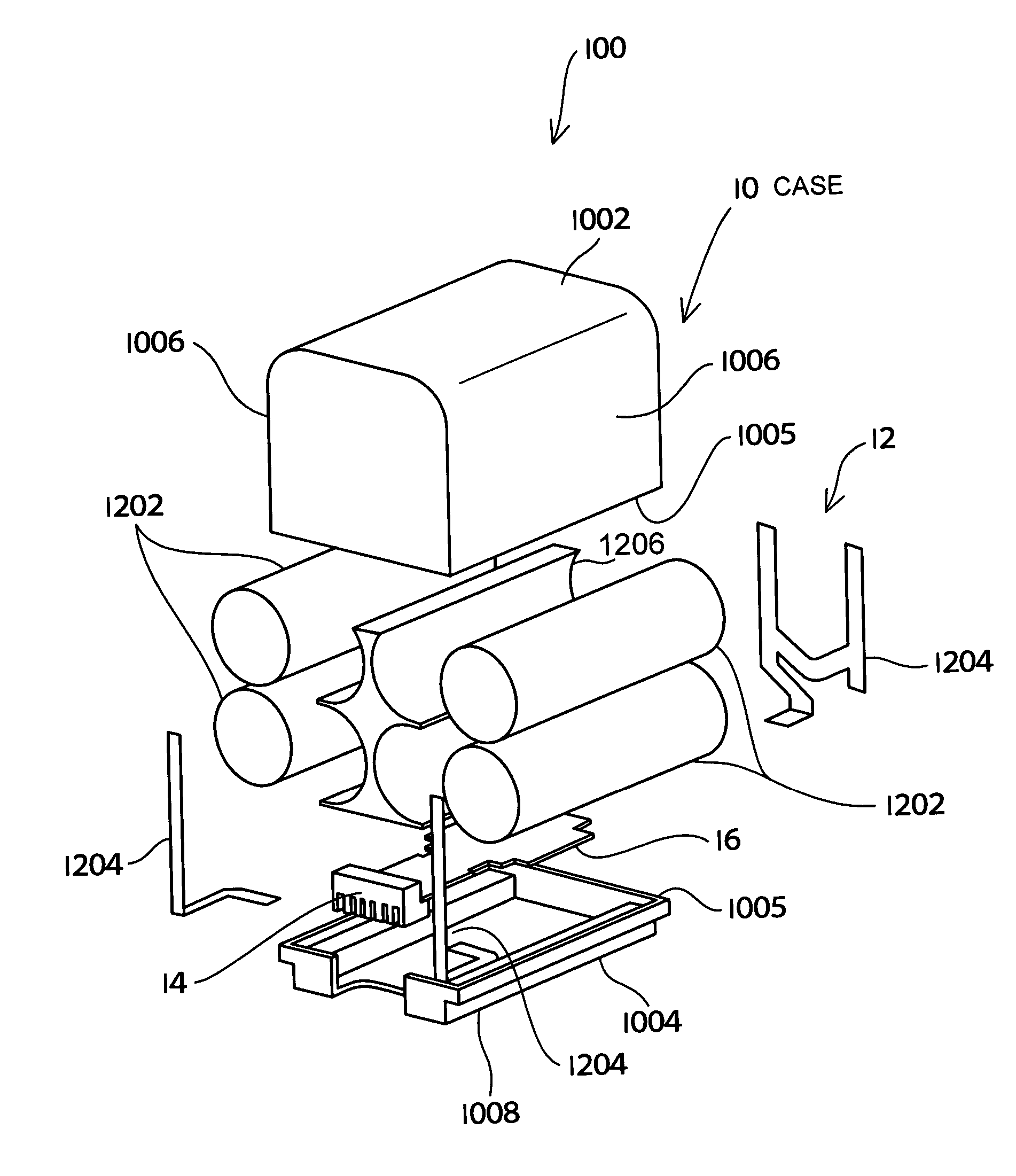
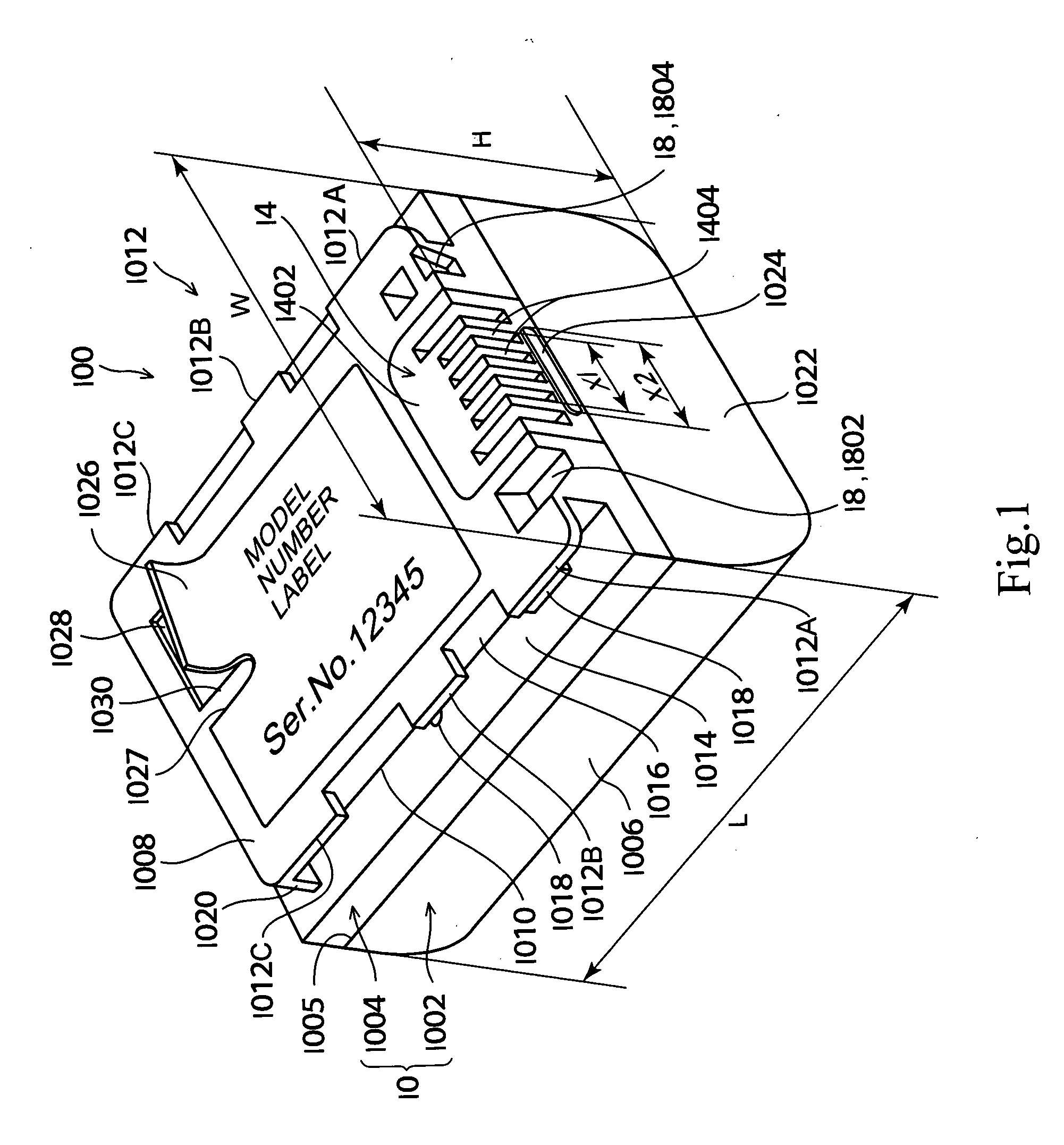
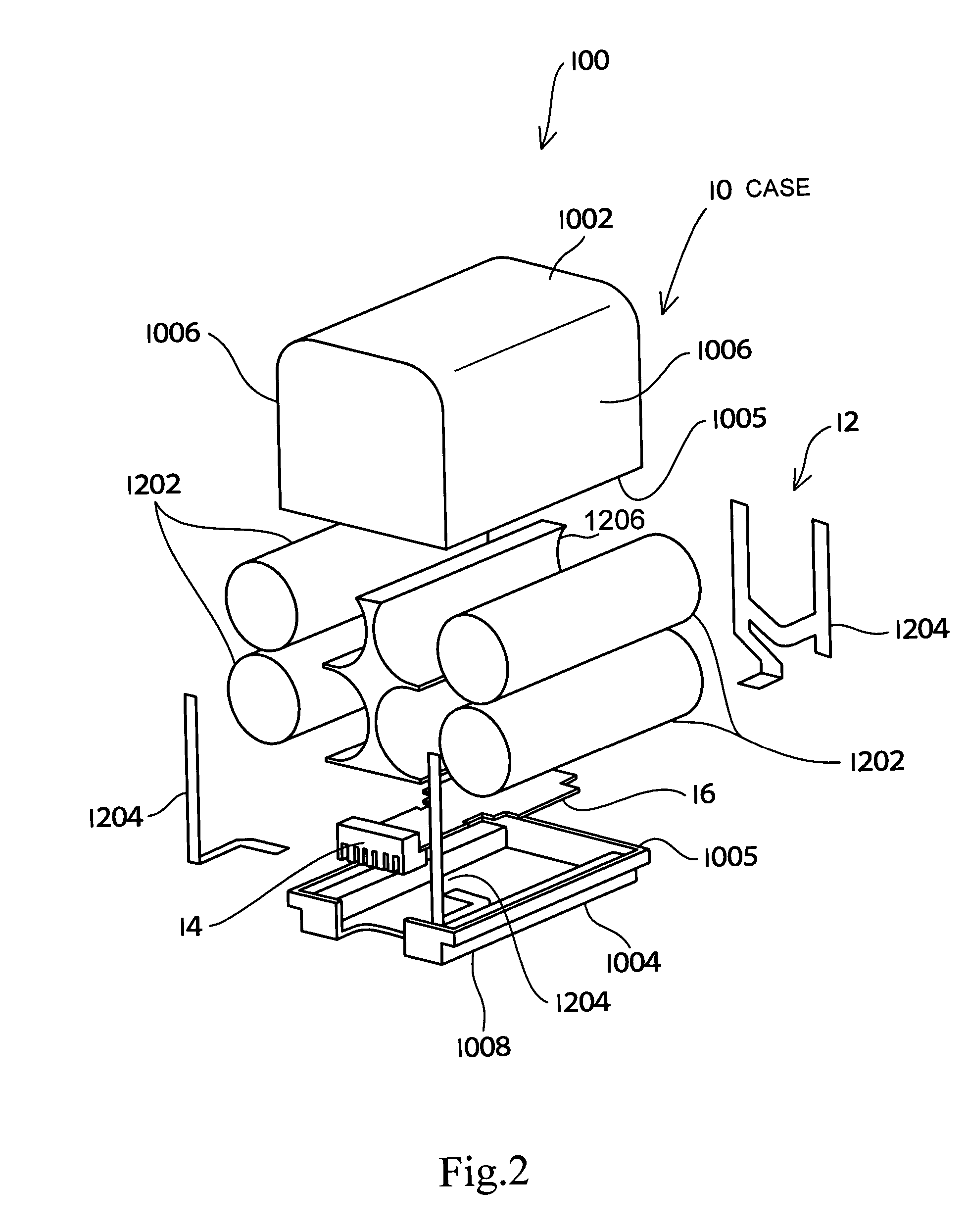
[0039]FIG. 1 is a perspective view of a battery apparatus of Embodiment 1, as viewed from the bottom thereof, and FIG. 2 is an exploded perspective view showing a configuration of the battery apparatus of Embodiment 1.

[0040] First, the battery apparatus will be described.

[0041] As shown in FIG. 1, a battery apparatus 100 includes a case 10, a rechargeable battery section 12 (see FIG. 2) provided inside the case 10, a control circuit board 16 provided inside the case 10, a battery-side terminal 14 provided on the case 10, and an identification section 18.

[0042] As shown in FIG. 2, the rechargeable battery section 12 has four column-shaped battery cells 1202, a plurality of wiring members 1204 for conne...

embodiment 2

[0129] Next, Embodiment 2 of the present invention will be described with reference to the drawings.

[0130] Embodiment 2 differs from Embodiment 1 in that the electronic equipment is a battery charger and that detection means for detecting the identification section 18 of the battery apparatus 100 is provided.

[0131]FIGS. 17, 18 are explanatory diagrams showing states in which four types of battery apparatus 100 (100A, 100B, 100C, 100D), each having a different capacity or charging current for supply during charge, are attached to a battery charger 400.

[0132]FIG. 19 is a block diagram showing a configuration of the battery apparatus 100, and the battery charger 400 as the electronic equipment. In the following, the same or similar parts as in Embodiment 1 are denoted by the same reference symbols, and their descriptions are omitted.

[0133] Note that FIGS. 17(A), (B), and FIGS. 18(C), (D) are perspective diagrams of battery-side terminals 14. FIGS. 17(A1), (B1) are views on arrow X1...


PUM

PropertyMeasurementUnit
angleaaaaaaaaaa
lengthaaaaaaaaaa
distanceaaaaaaaaaa

Abstract

A battery apparatus and electronic equipment, in which the battery apparatus having a characteristic compatible with the electronic equipment can be suitably attached to the electronic equipment, and which are advantageous in miniaturizing themselves and improving their operability. In a battery apparatus (100), an identification section (18) of the battery apparatus (100) serves to identify a characteristic of the battery apparatus (100), and which is provided on an end surface (1022) and on both sides of a battery-side terminal (14) in the width direction (W) of the battery apparatus (100). The identification section (18) is configured with identification recesses (1802), (1804) formed in a manner open to the end surface (1022), and at least one of the positions, cross-sectional shapes, and lengths on the end surface (1022) of the identification recesses (1802), (1804) is formed on the basis of the characteristic of the battery apparatus. In the identification (18), the cross-sectional shape and length of the identification recess (1802) is formed on the basis of the characteristic of the battery apparatus (100).

Description

TECHNICAL FIELD [0001] The present invention relates to a battery apparatus, and electronic equipment which operates by the battery apparatus. BACKGROUND ART [0002] There have been provided a battery apparatus, and electronic equipment which has a battery attachment section to which the battery apparatus is attached, and operates by power supplied from the battery apparatus (see, e.g., Japanese Patent Publication No. 2508447). [0003] If the electronic equipment is to be used by attaching the battery apparatus thereto, it is required that a battery apparatus having a capacity suitable for a current to be consumed by the electronic equipment be attached to the electronic equipment. Therefore, it is preferable to permit attachment of only a battery apparatus having a suitable capacity, to the battery attachment section, and not to permit attachment of a battery apparatus not having a suitable capacity. [0004] Thus, conventionally, e.g., around the middle of an attachment surface of the...

Claims


Application Information

Patent Timeline
Patent Type & Authority Applications(United States)
IPC IPC(8): H01M2/30H01M10/48H04N5/225H01M10/42H01M10/46H01M50/107
CPCH01M2/1066H01M2/30H01M2220/30H01M10/46H01M2/1055H01M10/42Y02E60/10Y02P70/50H01M50/107H01M50/20H01M50/10H01M50/213
Inventor TAKESHITA, TOSHIOTASHIRO, KEIKONDOU, TAKASHITAMESUE, YOSHIHITO
Owner SONY CORP
Features
  • R&D
  • Intellectual Property
  • Life Sciences
  • Materials
  • Tech Scout
  • Unparalleled Data Quality
  • Higher Quality Content
  • 60% Fewer Hallucinations
Learn More