Method and system for antenna geometry for multiple antenna handsets

a technology of antenna geometry and handsets, applied in the field of wireless handsets, can solve the problem of transmission signals being susceptible to fading

Inactive Publication Date: 2007-07-12
AVAGO TECH INT SALES PTE LTD
View PDF8 Cites 4 Cited by
  • Summary
  • Abstract
  • Description
  • Claims
  • Application Information

AI Technical Summary

Benefits of technology

[0028] A system and/or method for a method and system for antenna geometry for multiple antenna handsets, substantially

Problems solved by technology

However, transmitted signals are susceptible to fading, especially since the mobil

Method used


Image

  • Method and system for antenna geometry for multiple antenna handsets
  • Method and system for antenna geometry for multiple antenna handsets
  • Method and system for antenna geometry for multiple antenna handsets

Examples


Embodiment Construction

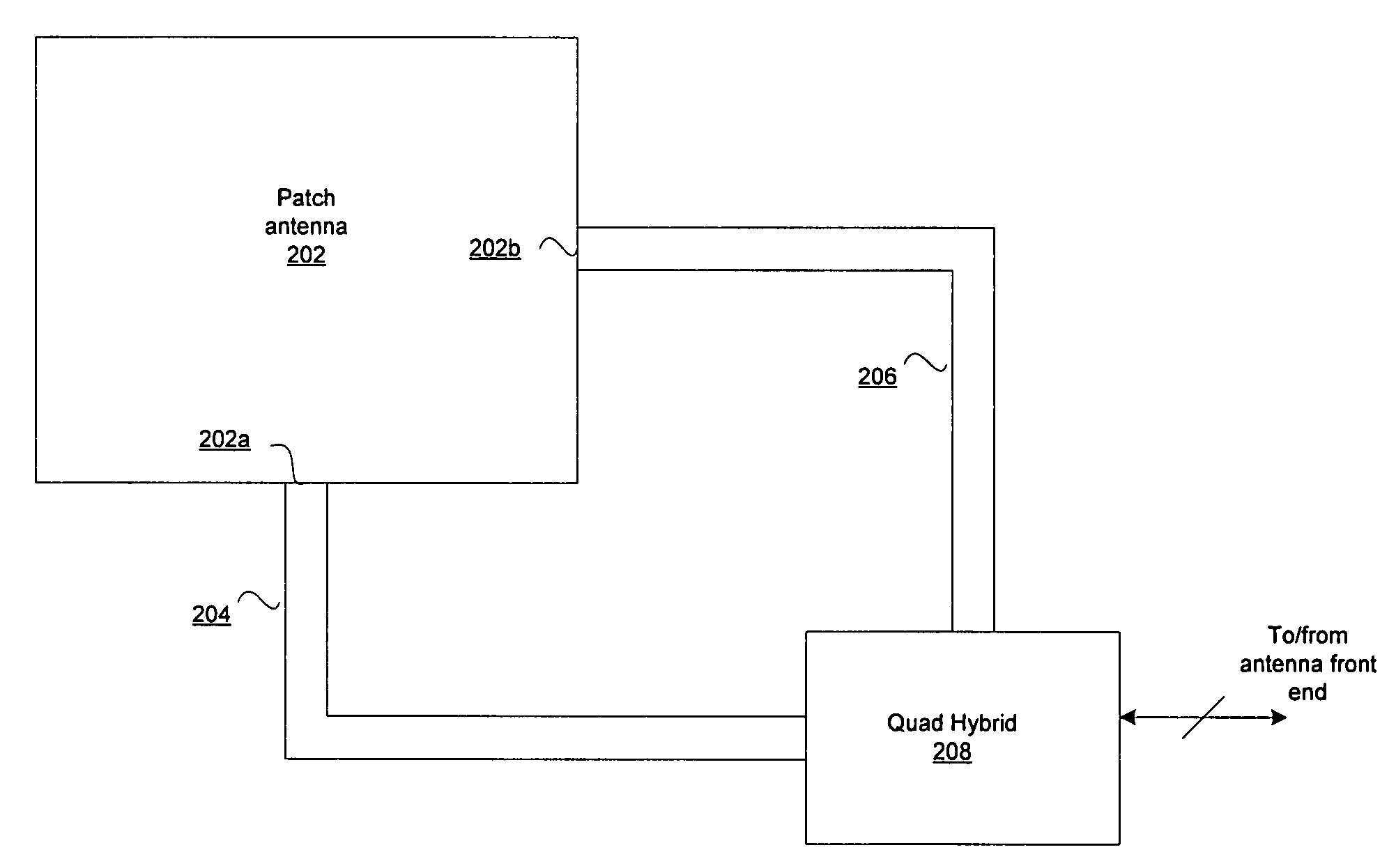
[0040] Certain embodiments of the invention may be found in a method and system for antenna geometry for multiple antenna handsets. Aspects of the method may comprise receiving RF signals via a patch antenna coupled to a signal processing circuitry within a mobile terminal. The dimensions of the patch antenna may be chosen so as to optimize the patch antenna for receiving and / or transmitting information bearing signals at certain frequencies. The signal processing circuitry may process the RF signals, which may comprise at least one of a plurality of polarizations. The patch antenna may be a dual-polarized antenna, and may comprise a plurality of ports. RF signals at a first of the plurality of ports may be orthogonally polarized to RF signals at a second of the plurality of ports. The patch antenna may be optimized to simultaneously receive multiple RF bands. This may be accomplished by optimizing one dimension of the patch antenna for one RF band and optimizing another dimension o...


PUM


Abstract

Certain embodiments for antenna geometry for multiple antenna handsets may include receiving RF signals via a patch antenna coupled to a signal processing circuitry within a mobile terminal. The signal processing circuitry may process the RF signals, comprising at least one of a plurality of polarizations that are received by the patch antenna. The patch antenna may be a dual-polarized antenna, and may comprise a plurality of ports. RF signals at a first of the plurality of ports may be orthogonally polarized with respect to RF signals at a second of the plurality of ports. The patch antenna may be optimized to receive multiple RF bands. Each of the multiple RF bands may be communicated via different ports to be processed.

Description

CROSS-REFERENCE TO RELATED APPLICATIONS / INCORPORATION BY REFERENCE [0001] This application makes reference to: [0002] U.S. patent application Ser. No. 11 / 010,991, filed Dec. 13, 2004; [0003] U.S. patent application Ser. No. 11 / 010,847, filed Dec. 13, 2004; [0004] U.S. patent application Ser. No. 11 / 010,461, filed Dec. 13, 2004; [0005] U.S. patent application Ser. No. 11 / 010,877, filed Dec. 13, 2004; [0006] U.S. patent application Ser. No. 11 / 010,914, filed Dec. 13, 2004; [0007] U.S. patent application Ser. No. 11 / 010,486, filed Dec. 13, 2004; [0008] U.S. patent application Ser. No. 11 / 010,903, filed Dec. 13, 2004; [0009] U.S. patent application Ser. No. 11 / 011,009, filed Dec. 13, 2004; [0010] U.S. patent application Ser. No. 11 / 010,855, filed Dec. 13, 2004; [0011] U.S. patent application Ser. No. 11 / 010,743, filed Dec. 13, 2004; [0012] U.S. patent application Ser. No. 11 / 010,983, filed Dec. 13, 2004; [0013] U.S. patent application Ser. No. 11 / 011,000, filed Dec. 13, 2004; [0014] U.S...

Claims


Application Information

Patent Timeline
IPC IPC(8): H01Q1/38
CPCH01Q9/0435
Inventor ROOYEN, PIETER VAN
Owner AVAGO TECH INT SALES PTE LTD
Why Eureka
Try Eureka