Voltage generating system

a voltage generation system and voltage generation technology, applied in the direction of electric generator control, dynamo-electric converter control, instruments, etc., can solve the problems of insufficient operation of electric-luminescent display devices or the like, and may not meet the criterion, so as to eliminate the variation in output voltage, suppress the circuit area and power consumption, and eliminate the effect of output voltage variation

Inactive Publication Date: 2007-07-12
PANASONIC SEMICON SOLUTIONS CO LTD
View PDF12 Cites 0 Cited by
  • Summary
  • Abstract
  • Description
  • Claims
  • Application Information

AI Technical Summary

Benefits of technology

[0014] Thus, the first and second voltage generating devices output the same voltage which is generated by one of the first and second voltage generating devices. Therefore, when a voltage is output from each of the two voltage generating devices, it is possible to eliminate a variation in output voltage between these voltage generating devices. Also, it is sufficient to use all of two voltage generating devices to generate required voltages, thereby making it possible to suppress the circuit area and the power consumption.
[0016] Thereby, it is possible to eliminate a variation in output voltage between the first to third voltage generating devices.
[0017] According to the present invention, when a voltage is output from each of a plurality of voltage generating devices, it is possible to eliminate a variation in output voltage between the voltage generating devices. Further, it is sufficient to use all of a plurality of voltage generating devices to generate required voltages, thereby making it possible to suppress the circuit area and the power consumption. Furthermore, a circuit for driving a display device is simplified, thereby making it possible to reduce a size (width) of a frame around a screen of a liquid crystal display device, an EL display device or the like.

Problems solved by technology

When a current output-type semiconductor circuit outputs a small current, charging and discharging of a source signal line of a liquid crystal display driver, an electro-luminescent (EL) display device or the like cannot be sufficiently performed.
However, according to the configuration of FIG. 14, this criterion may not be satisfied due to a variation in semiconductor process.

Method used


Image

  • Voltage generating system
  • Voltage generating system
  • Voltage generating system

Examples


first embodiment

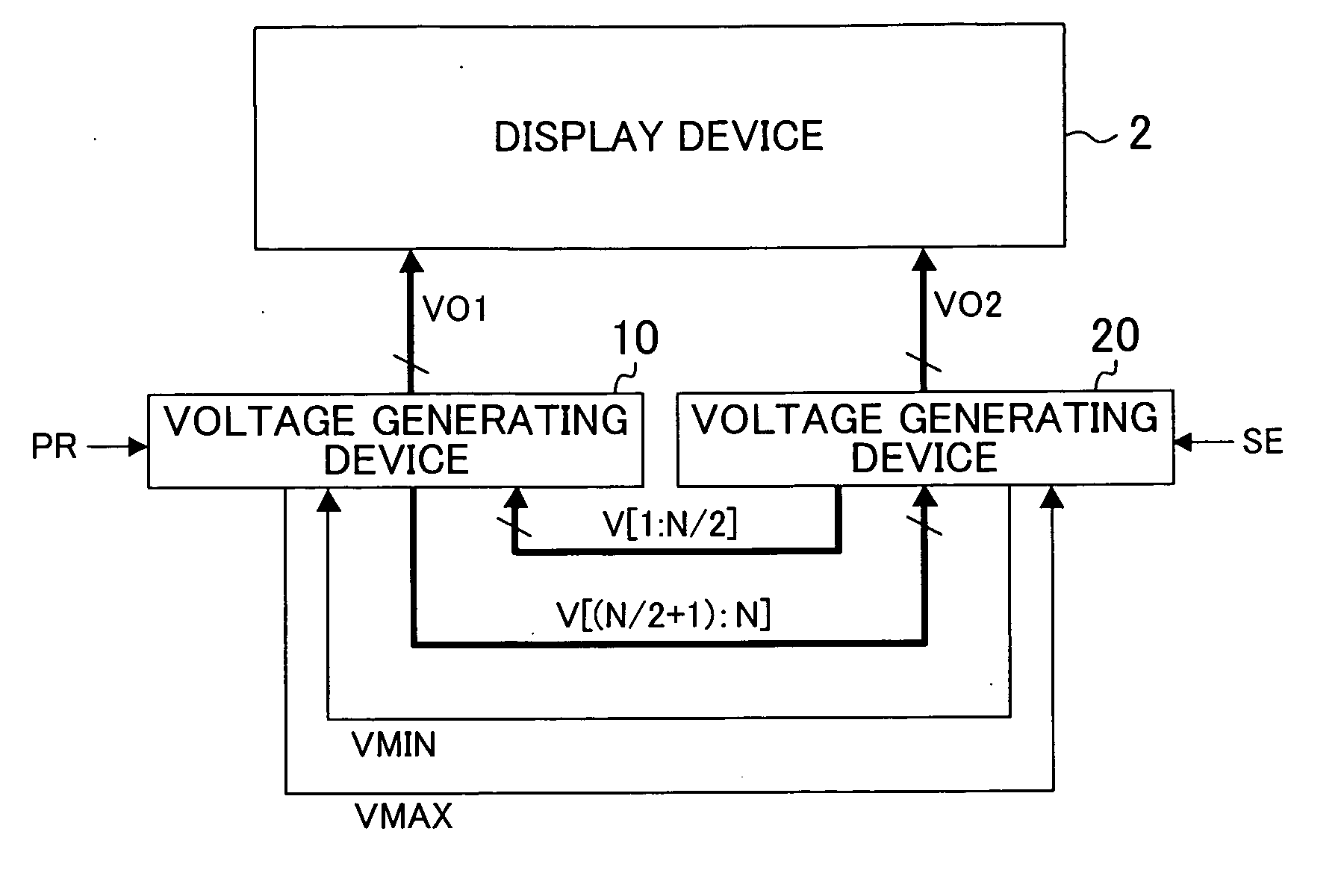
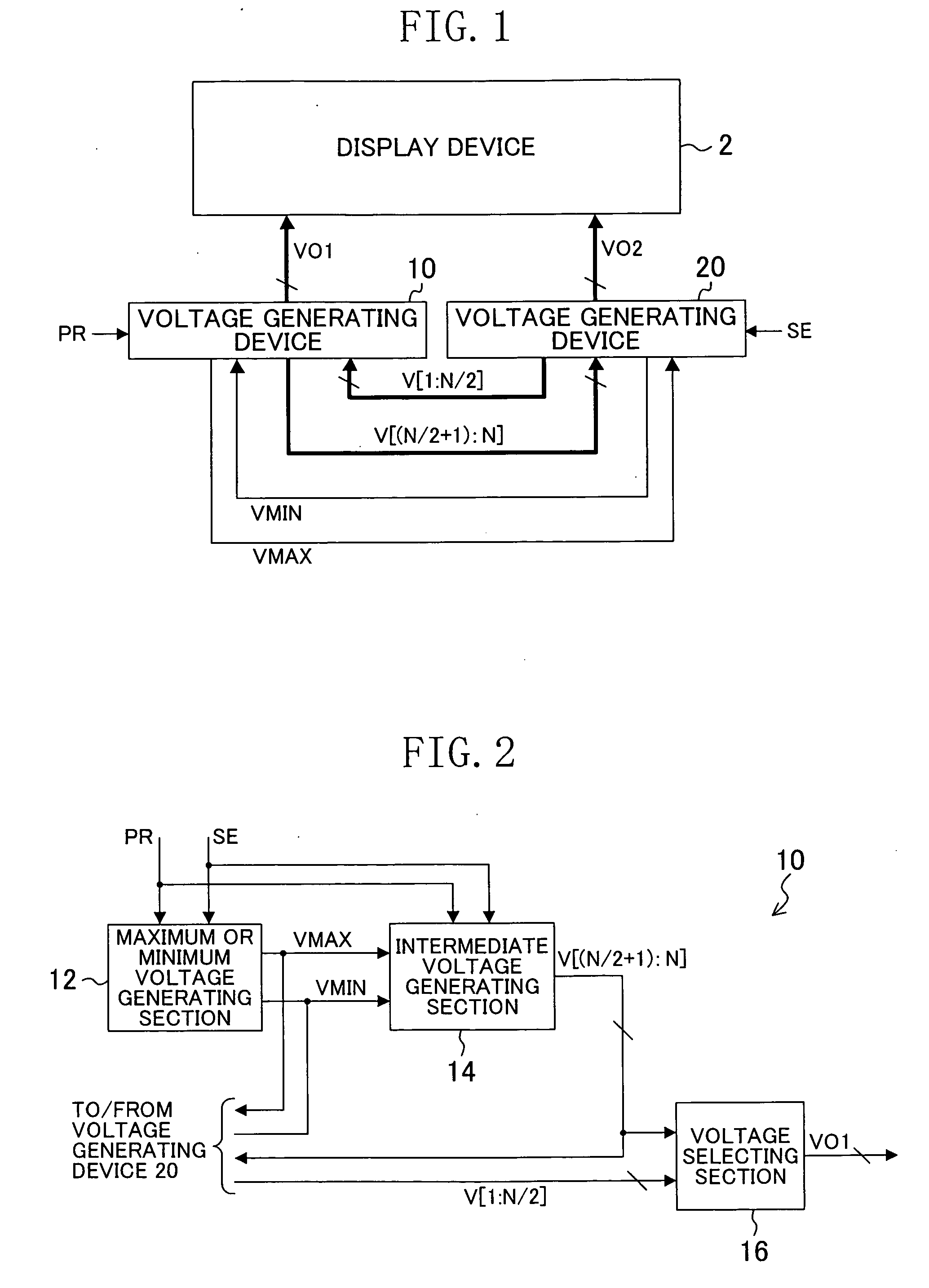
[0034]FIG. 1 is a block diagram illustrating a configuration of a voltage generating system according to a first embodiment of the present invention. The voltage generating system of FIG. 1 comprises voltage generating devices 10 and 20. The voltage generating 20 device 10 generates and supplies a maximum voltage VMAX to the voltage generating device 20. The voltage generating device 20 generates and outputs a minimum voltage VMIN to the voltage generating device 10.

[0035] Based on the maximum voltage VMAX and the minimum voltage VMIN, the voltage generating device 10 generates a plurality of voltages between these voltages, and supplies the generated voltages as voltages V[(N / 2+1):N] (N is an integer of two or more) to the voltage generating device 20. Based on the maximum voltage VMAX and the minimum voltage VMIN, the voltage generating device 20 generates a plurality of voltages (voltages different from the voltages V[(N / 2+1):N]) between these voltages, and outputs the generated...

second embodiment

[0070]FIG. 11 is a block diagram illustrating a configuration of a voltage generating system according to a second embodiment of the present invention. The voltage generating system of FIG. 11 comprises voltage generating devices 510, 520 and 530. The voltage generating device 510 generates and supplies a maximum voltage VMAX to the voltage generating devices 520 and 530. The voltage generating device 520 generates and supplies a minimum voltage VMIN to the voltage generating devices 510 and 530.

[0071] Based on the maximum voltage VMAX and the minimum voltage VMIN, the voltage generating device 510 generates a plurality of voltages between these voltages, and supplies the generated voltages as voltages V[(2N / 3+1):N] to the voltage generating devices 520 and 530. Based on the maximum voltage VMAX and the minimum voltage VMIN, the voltage generating device 520 generates a plurality of voltages (voltages different from the voltages V[(2N / 3+1):N]) between these voltages, and outputs th...


PUM


Abstract

A voltage generating system has a first voltage generating device for generating a plurality of voltages between a maximum voltage and a minimum voltage as a first set of voltages, and a second voltage generating device for generating a plurality of voltages between the maximum voltage and the minimum voltage as a second set of voltages, the second set of voltages being different from the first set of voltages. The first voltage generating device generates the maximum voltage, and supplies the first set of voltages and the maximum voltage to the second voltage generating device. The second voltage generating device generates the minimum voltage, and supplies the second set of voltages and the minimum voltage to the first voltage generating device. The first and second voltage generating devices each select a voltage from the first and second sets of voltages, and output the selected voltage.

Description

CROSS REFERENCE TO RELATED APPLICATIONS [0001] This Non-provisional application relates to Patent Application No. 2006-345921 filed in Japan on Dec. 22, 2006, the entire contents of which are hereby incorporated by reference.BACKGROUND OF THE INVENTION [0002] The present invention relates to a voltage generating system for generating a plurality of voltages. [0003] There is a known power supply circuit which uses a single integrated circuit (IC) to generate and supply a plurality of voltages to a display device or the like. The power supply circuit controls each voltage, depending on whether or not a device to which the voltage is supplied is operating (see, for example, Japanese Unexamined Patent Application Publication No. 2001-236127). [0004] When a current output-type semiconductor circuit outputs a small current, charging and discharging of a source signal line of a liquid crystal display driver, an electro-luminescent (EL) display device or the like cannot be sufficiently perf...

Claims


Application Information

Patent Timeline
Patent Type & Authority Applications(United States)
IPC IPC(8): G09G5/00
CPCG09G2310/027G09G3/20
Inventor KOJIMA, TOMOKAZUKOJIMA, HIROSHIOMORI, TETSURO
Owner PANASONIC SEMICON SOLUTIONS CO LTD
Why Eureka
Try Eureka