Method of Maintaining Eye Contact in Video Conferencing Using View Morphing

a video conferencing and eye contact technology, applied in the field of video conferencing, can solve the problems of distracting the local participant, unsatisfactory user experience, and bulky devices both aesthetically and physically cumbersome, and achieve the effect of enhancing the eye contact sens

Inactive Publication Date: 2007-07-12
APPLIED INVENTION
View PDF9 Cites 52 Cited by
  • Summary
  • Abstract
  • Description
  • Claims
  • Application Information

AI Technical Summary

Benefits of technology

[0018] To resolve the identified problems found in the prior art, the present invention creates a head-on view of a local participant, thereby enhancing the sense of eye contact provided during any of the following: a video conference session, a video phone session, a session at a video kiosk, and a video training session. Note that video conference sessions include, but are not limited to, sessions presented via one or more private communications channels and sessions presented via one or more broadcast channels.
[0019] A view morphing algorithm is applied to a synchronous collection of images from at least two video imaging devices. These images are interpolated to create interpolation images for each of the video imaging devices. The interpolated images from at least two of the video imaging devices are combined to create a composite image of the local participant. This composite image approximates a head-on view of the local participant providing excellent eye contact.
[0023] This head-on view of the local participant supports the local participant looking directly at the monitor and provides a sense of eye contact when viewed by the second participant, actively aiding the sense of personal interaction for all participants.
[0024] Certain embodiments of the invention include, but are not limited to, various schemes supporting generation of the composite image, control of composite image generation by at least one of the second participants, and adaptively modifying the current images at certain stages based upon remembered displacements from previous images. These embodiments individually and collectively aid in improving the perceived quality of eye contact.

Problems solved by technology

Since participants frequently look at the monitor, either at the image of the second participant or elsewhere on the display, rather than directly at the video camera, there is the appearance that the participants are not looking at one another, resulting in an unsatisfactory user experience.
In devices incorporating a conventional CRT, the resulting device is both aesthetically bulky and physically cumbersome.
Furthermore, in cases involving an upward facing display, the display is viewable both directly and as reflected by the beamsplitter, greatly distracting the local participant.
The resulting distant appearance of the second participant greatly diminishes the sense of intimacy sought during videoconferencing.
The resulting image, with artificially generated eyes and a slight but frequent mismatch between the position of the eyes relative to the head and body of the participant, is unnatural in appearance.
Furthermore, the creation of an intermediate three-dimensional model is computationally intensive, making it difficult to implement in practice.
This presents a significant obstacle to introduction and widespread adoption of the device.

Method used


Image

  • Method of Maintaining Eye Contact in Video Conferencing Using View Morphing
  • Method of Maintaining Eye Contact in Video Conferencing Using View Morphing
  • Method of Maintaining Eye Contact in Video Conferencing Using View Morphing

Examples


Embodiment Construction

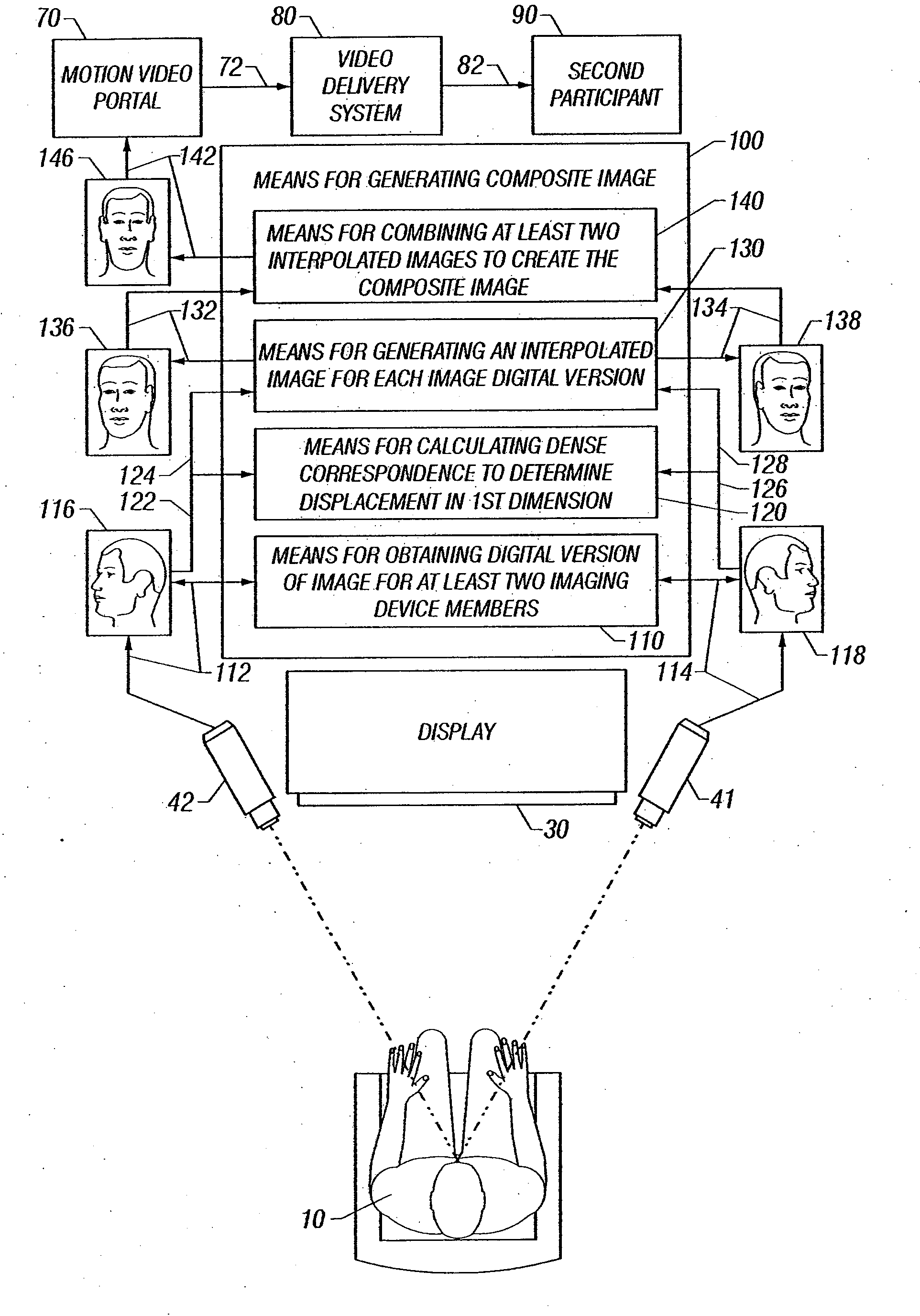
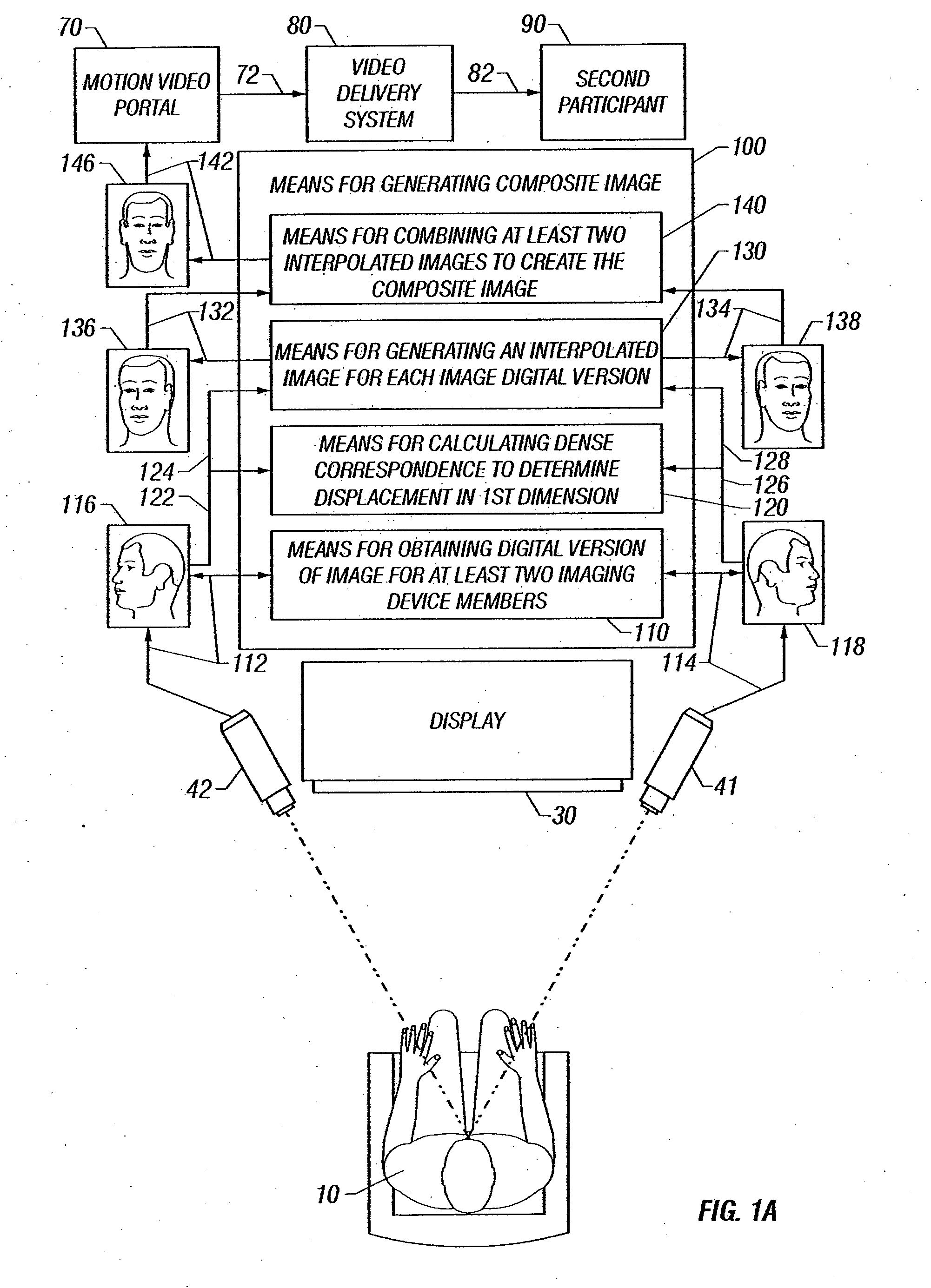
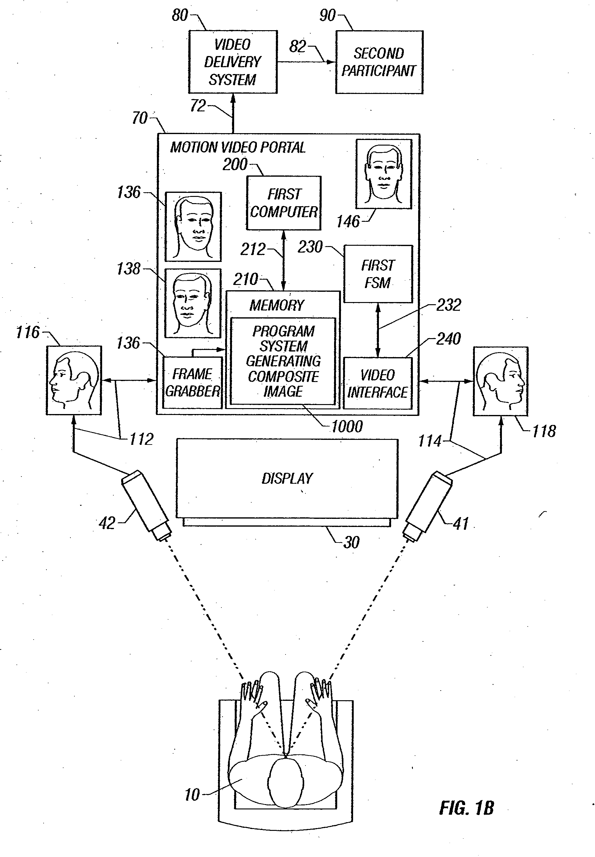
[0057]FIG. 1A shows a simplified block diagram overview of the invention, including local participant 10, video display 30, pair of imaging devices 41 and 42, means for generating composite image 100, motion video portal 70, video delivery system 80 and second participant 90.

[0058] Means 100 for generating composite image 146 is communicatively coupled 114 and 112 with at least two imaging device collection members 41 and 42, respectively. Means 100 regularly receives an image 118 and 116 from each of the at least two imaging device collection members 41 and 42, respectively, to provide a synchronized collection of images based upon observations of at least the local participant's head 10 by the imaging devices.

[0059] Means 100 for generating composite image 146 is communicatively coupled 142 to motion video portal 70, providing a succession of composite images 146, each based upon at least synchronized image collection 116 and 118 to 72 video delivery system 80.

[0060] Video deli...


PUM


Abstract

A view morphing algorithm is applied to synchronous collections of video images from at least two video imaging devices, and interpolating between the images, creates a composite image view of the local participant. This composite image approximates what might be seen from a point between the video imaging devices, presenting the image to other video session participants.

Description

CROSS-REFERENCE TO RELATED APPLICATIONS [0001] This application is a Continuation of U.S. patent application Ser. No. 10 / 691,930 filed Oct. 22, 2003, which claims priority to U.S. patent application Ser. No. 09 / 995,272, filed on Nov. 27, 2001, which claims priority to Provisional Application Ser. No. 60 / 250,955, filed on Nov. 29, 2000.BACKGROUND OF THE INVENTION [0002] 1. Technical Field [0003] This invention relates to the field of video conferencing and in particular to methods and systems maintaining the appearance of eye contact between communicants in a teleconference. [0004] 2. Background Art [0005] A primary concern with video teleconferencing systems is the frequent lack of eye contact between participants. In the most common configuration, each participant uses a computer monitor on which an image of the second participant is displayed, while a camera mounted above the monitor captures the image of the local participant for display on the monitor of the second participant. ...

Claims


Application Information

Patent Timeline
Patent Type & Authority Applications(United States)
IPC IPC(8): H04N7/14
CPCH04N7/15H04N7/144
Inventor HILLIS, W. DANIELFERREN, BRANHOWE, RUSSEL
Owner APPLIED INVENTION
Why Eureka
Try Eureka