
Device and method for manufacturing an electro-active spectacle lens involving a mechanically flexible integration insert

a technology of electro-active spectacles and integration inserts, applied in the field of electro-active spectacle lenses, can solve the problems of inability to focus on near objects, objectionable to some patients, blurred and distorted vision,

Inactive Publication Date: 2007-07-12
PIXELOPTICS
View PDF99 Cites 75 Cited by
  • Summary
  • Abstract
  • Description
  • Claims
  • Application Information

AI Technical Summary

Problems solved by technology

Presbyopia is the loss of accommodation of the crystalline lens of the human eye, a condition that results in the inability to focus on near objects.
There are issues associated with these two approaches that can be objectionable to some patients.
The visible line of demarcation associated with bifocals can be aesthetically displeasing and the transition regions associated with progressive lenses can lead to blurred and distorted vision, which, in some patients, can lead to physical discomfort.
Furthermore, the placement of the near vision correction area near the bottom edge of the lens requires patients to adopt a somewhat unnatural downward gaze for near vision tasks.
While many technologies could be approached as a solution to the problem, the rather restrictive form factor of spectacles and the need for low electrical power consumption limit what is feasible.

Method used


Image

  • Device and method for manufacturing an electro-active spectacle lens involving a mechanically flexible integration insert
  • Device and method for manufacturing an electro-active spectacle lens involving a mechanically flexible integration insert
  • Device and method for manufacturing an electro-active spectacle lens involving a mechanically flexible integration insert

Examples


Embodiment Construction

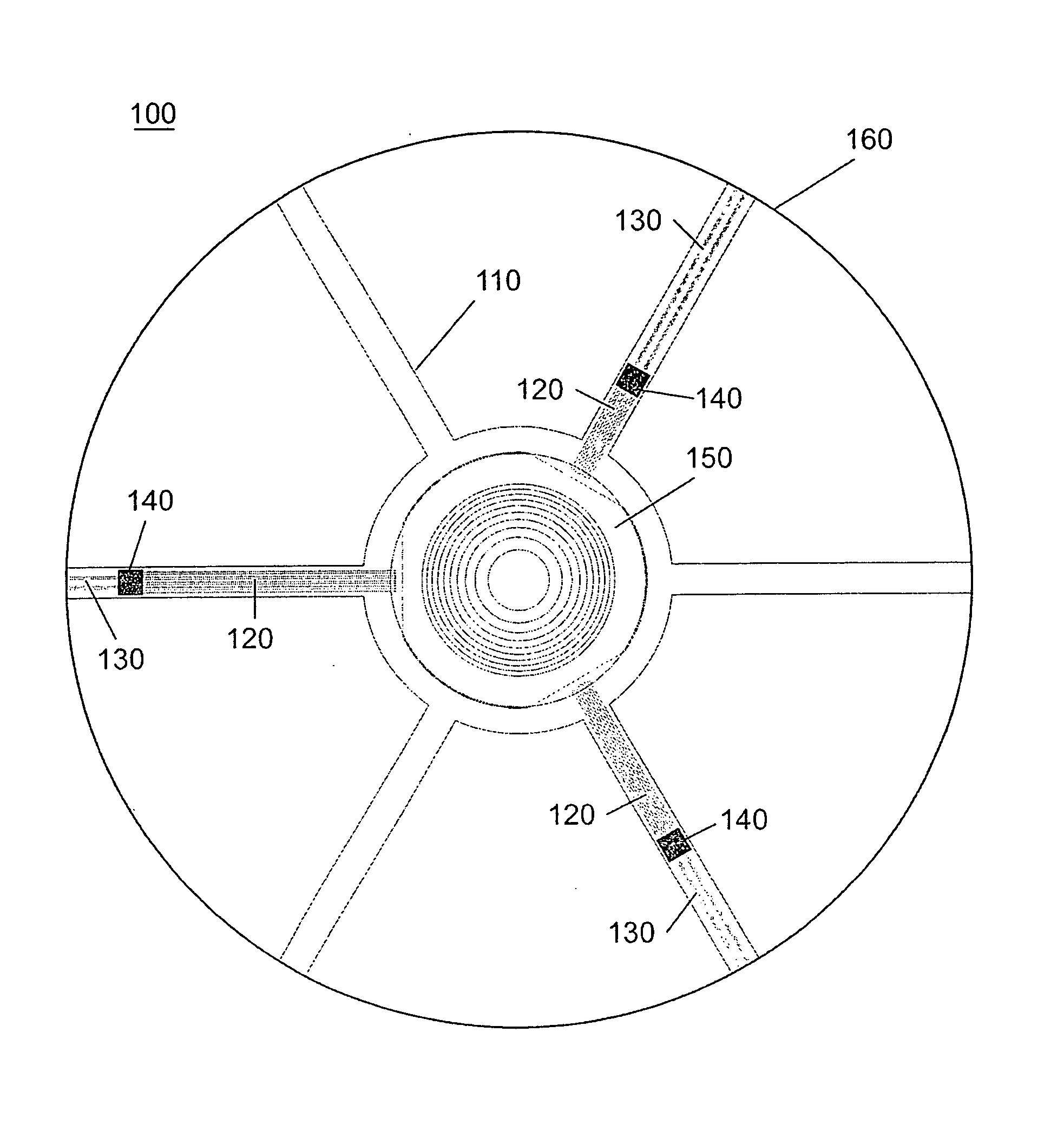
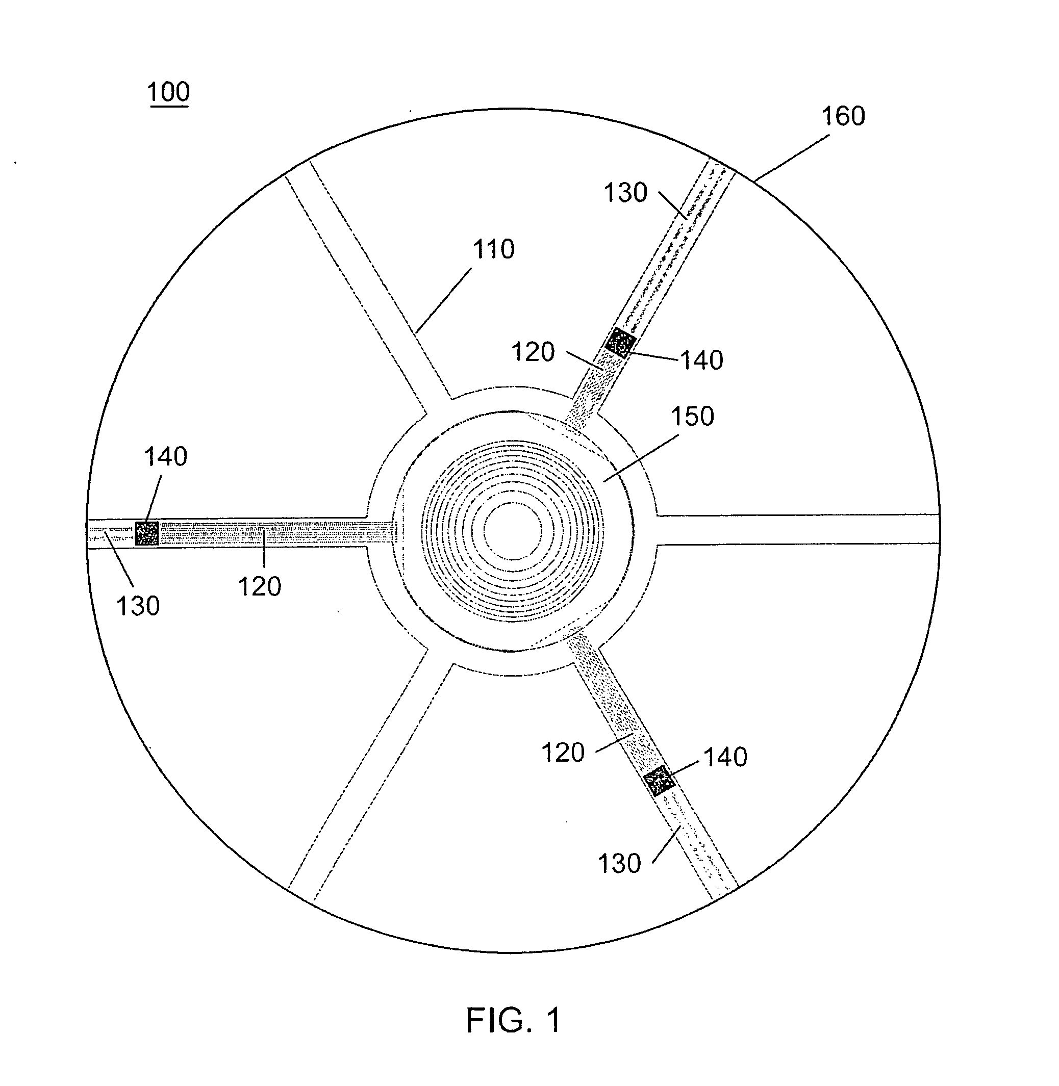
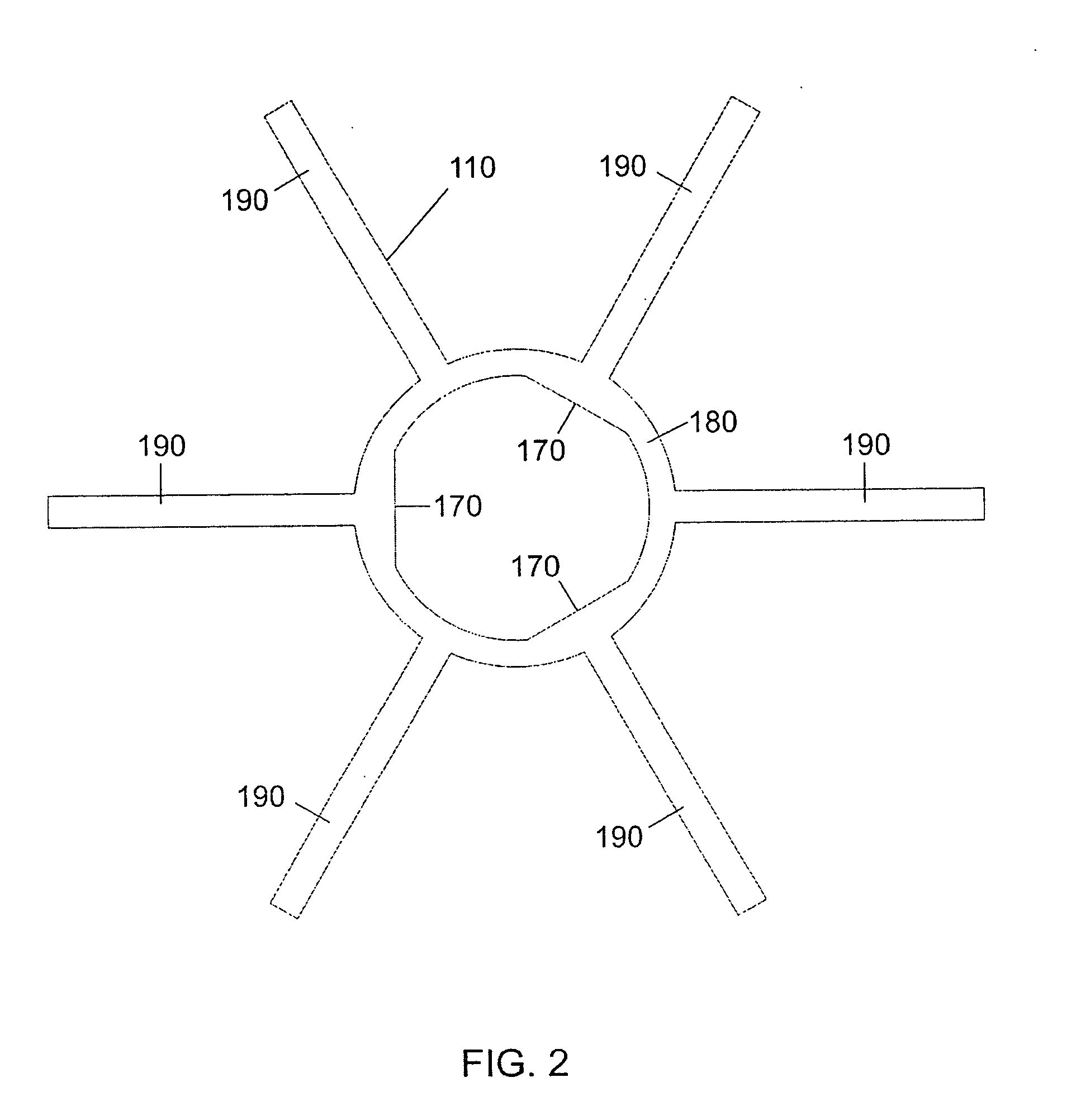
[0048] A top view drawing of an electro-active (EA) spectacle lens 100 manufactured by the proposed methods is shown in FIG. 1. This lens includes an integration insert 100 possessing transparent, thin film signal electrical leads 120 and battery electrical leads 130, to which an electro-active (EA) optical element 150 and integrated circuits 140 are attached. FIG. 2 shows the integration insert without any of the thin film electrical leads or integrated circuits applied. The central ring 180 and “arms”190 of the integration insert 110 act to provide physical support when incorporating the EA element 150 within the bulk refractive optical element 160 and provide a platform for attaching transparent electrical leads 120 and 130 and integrated circuits 140 which are needed to operate the EA element. The EA element may have planar surfaces, curved surfaces or may be designed such that one surface is planar and the other is curved. In most but not all cases these surfaces are equidistan...


PUM


Abstract

An improved device and method for manufacturing electro-active spectacle lenses comprising electronic, electro-active optical, and bulk refractive optical elements is presented. In this method, electronic and electro-active optical elements are mounted to an optically transparent and mechanically flexible integration insert which is separate from any bulk refractive optical element(s). This method is advantageous for the manufacture of such spectacle lenses in that it allows for the mass production of many of the individual elements and enables the integration of the insert with the bulk refractive optical element(s) by multiple means. One such approach involves attaching the insert with a transparent adhesive to a rigid optical substrate and then encapsulating it by means of surface casting. Alternatively, the insert may be placed between the surfaces of a mold filled with an optical resin and encapsulated within the bulk refractive element as the resin is cured.

Description

CROSS REFERENCE TO RELATED APPLICATIONS [0001] This application claims priority from and incorporates by reference in their entirety the following provisional applications: [0002] U.S. Ser. No. 60 / 757,382 filed on Jan. 10, 2006 and entitled “Improved method for manufacturing an electro-active spectacle lens involving a mechanically flexible integration insert”; and [0003] U.S. Ser. No. 60 / 759,814 filed on Jan. 19, 2006 and entitled “Improved method for manufacturing an electro-active spectacle lens involving a mechanically flexible integration insert”.BACKGROUND OF THE INVENTION [0004] 1. Field of the Invention [0005] The present invention relates to an electro-active spectacle lens and methods for manufacturing the electro-active spectacle lenses. [0006] 2. Description of the Related Art [0007] Presbyopia is the loss of accommodation of the crystalline lens of the human eye, a condition that results in the inability to focus on near objects. The standard tools for correcting presby...

Claims


Application Information

Patent Timeline
IPC IPC(8): G02F1/1335
CPCG02C7/08G02C7/083G02C7/101G02F1/1313B29D11/00817G02F1/134309G02F1/1345G02F1/13471G02F2203/18G02F1/133526G02C7/06G02C7/00G02F1/1335
Inventor HADDOCK, JOSHUA N.KOKONASKI, WILLIAMBLUM, RONALD D.IYER, VENKATRAMANI S.DUSTON, DWIGHT P.
Owner PIXELOPTICS
Learn More