

LED fiber decorative lamp structure
a technology of decorative lamps and fibers, applied in the field of decorative lamps, can solve the problems of noise generation, high temperature or burning, and complex structure of traditional fiber decorative lamps
- Summary
- Abstract
- Description
- Claims
- Application Information
AI Technical Summary
Benefits of technology
Problems solved by technology
Method used
Image

Examples
Embodiment Construction
[0030] Following are the detail descriptions of this invention
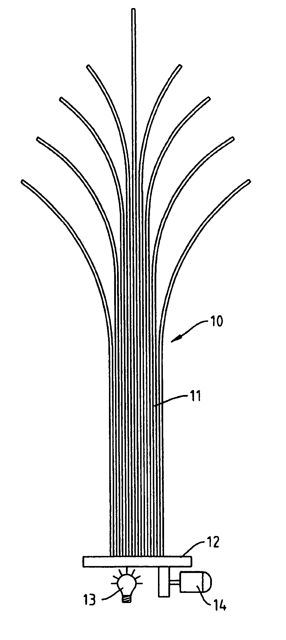
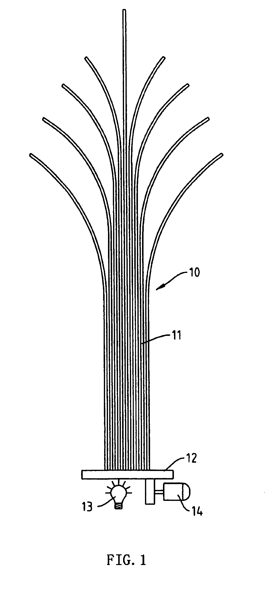
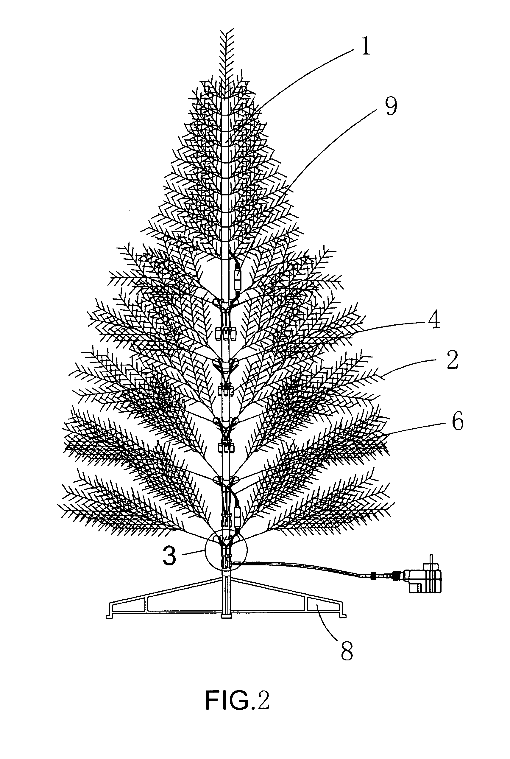
[0031] Like what showed from FIGS. 2 to 6, a LED fiber lamp structure comprises a base 1, a plurality of transparence devices 2 and a plurality of LED luminous section 8.
[0032] Base 1 can be placed on the ground for supporting. In this example of the Christmas tree, the base 1 is a trunk and several braches. A supporting device 8 can be set between the base and the ground, which enables the base 1 more stable.
[0033] A plurality of transparence devices 2 are mount on base 1 and form the whole shape of the LED fiber decorative lamp structure. The whole shape of the LED fiber decorative lamp structure can be image of animal, Christmas tree Santa Claus or Angell and so on. The animal can be deer, tiger, bear, fur seal or penguin etc. In this example, the transparence devices can be made into the Christmas tree branches and leaves with the transparence materials, and use sticking or the other method to fix them on base 1 to...
PUM
 Abstract
Description
Claims
Application Information