
Push-up dispenser

a dispenser and push-up technology, applied in the field of push-up dispensers, can solve the problems the cost of the dispenser, and achieve the effects of reducing the number of parts, and being convenient to us

Active Publication Date: 2007-07-12
COLGATE PALMOLIVE CO
View PDF34 Cites 10 Cited by
  • Summary
  • Abstract
  • Description
  • Claims
  • Application Information

AI Technical Summary

Benefits of technology

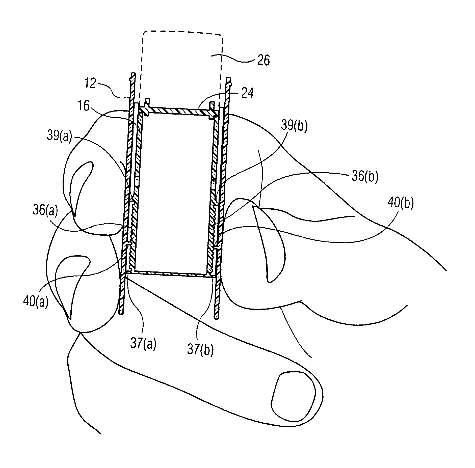
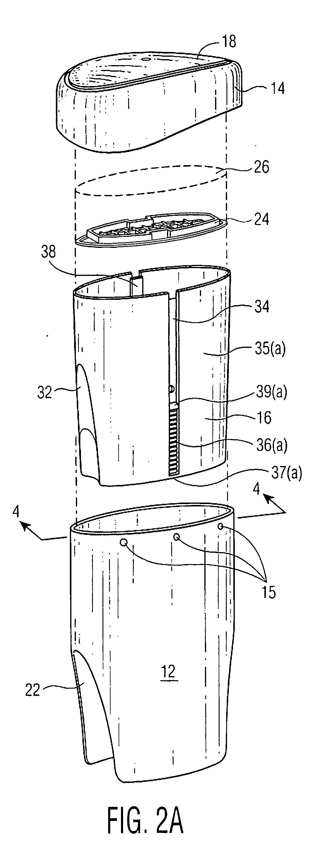
[0005] The present dispenser is adapted to minimize the parts that are needed while providing a dispenser that is easy to use. This also reduces the number of parts that need to be assembled. The dispenser comprises a first sleeve which is substantially open at the top and the bottom. A product support that includes a second sleeve which is received in the first sleeve. The second sleeve has a lower surface that is adapted to be contacted by a person's finger to adjust the second sleeve in the first sleeve. The inner surface of the first sleeve and the outer surface of the second sleeve have interfering structures such that when they are in contact the second sleeve is maintained in a set orientation, one to the other. This contact is the result of the first sleeve being pushed into contact with the second sleeve by the holding and gripping of the first sleeve. This contact can be enhanced through one or more apertures in the first sleeve walls to increase the flexibility of the first sleeve and consequently it's flexing against the second sleeve.

Problems solved by technology

The problem is to how best reduce the number of parts and the cost of the dispensers.
However the problem then is how to maintain the product at a selected level in the dispenser while the product is being applied to a surface.

Method used


Image

  • Push-up dispenser
  • Push-up dispenser
  • Push-up dispenser

Examples


Embodiment Construction

[0017] The invention will be described in more detail in its preferred embodiments with reference to Figures in the drawings. Modifications can be made to the disclosed embodiments but all such modifications are with the concept of the present invention.

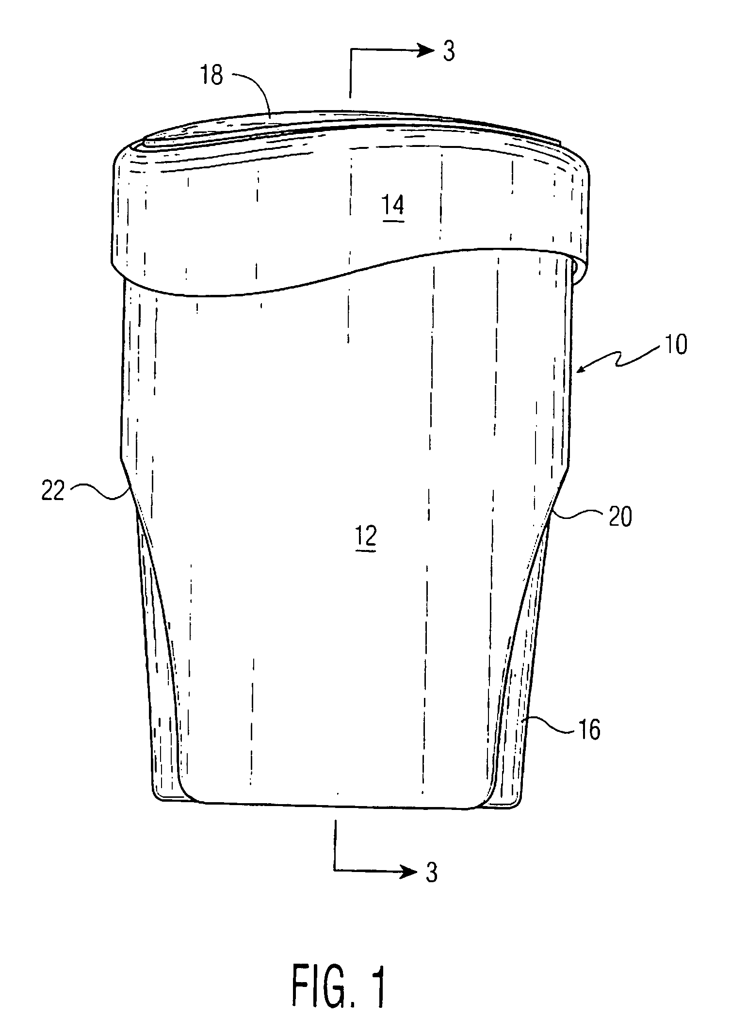
[0018]FIG. 1 is a front elevation view of the present dispenser 10. This dispenser 10 can be used to dispense solid and semi-solid products and is very useful for dispensing cosmetic products. These products include lipsticks, rouges, lip medications, deodorants and antiperspirants. The dispenser 10 is comprised of first sleeve 12, second sleeve 16 and closure 14. The closure has a top surface 18. The first sleeve has apertures 20 and 22 on the opposite side surfaces. The apertures extend from the lower surface of the first sleeve upwardly to increase the flexibility of the front and rear surfaces of the first sleeve. The apertures can be of essentially any shape depending on the increased flexibility that is desired. However an inv...


PUM


Abstract

The dispenser is comprised of a first sleeve that is substantially open at the top and the bottom. A product support is received into the first sleeve, this product support comprising a second sleeve. On the upper part of the second sleeve is a product supporting surface. The lower part of the second sleeve can be contacted by a person's finger to adjust the second sleeve within the first sleeve and to temporarily lock the second sleeve in the first sleeve. On the inner surface of the first sleeve and the outer surface of the second sleeve there are cooperating structures to maintain the second sleeve at a given position in the first sleeve upon the gripping of the first sleeve. The cooperating structure can be a cooperating serration structure on each sleeve, a serration structure on one sleeve and a locking projection on the other sleeve or any other interfering structure on each sleeve. In one embodiment there can be one or more apertures in the first sleeve to enhance to flexing of the first sleeve into contact with the second sleeve and the temporary locking of the second sleeve in the first sleeve. The product can be a cosmetic product which will include deodorants and antiperspirants. In use the second sleeve is adjusted within the first sleeve by pushing up on the bottom of the second sleeve. The sides of the first sleeve are gripped in an application grip which holds the second sleeve within the first sleeve during application of the product. Upon the relaxing of the grip the second sleeve can recede into the first sleeve and a closure put into place.

Description

FIELD OF THE INVENTION [0001] This invention relates to a push-up dispenser for solid and viscous products. More particularly this invention relates to a dispenser which can be maintained at the dispensing position by a gripping of the dispenser walls. BACKGROUND OF THE INVENTION [0002] Dispensing containers are used with regard to a number of cosmetic products. These include solid products such as lipsticks, deodorants and antiperspirants and various viscous lotion and gel products such as body lotions and gels, sunscreens, and deodorant and antiperspirant lotions and gels. Lipsticks are usually in a cylindrical form with a circular cross-section and are in a tubular container with a closure. The lipsticks are either manually elevated in the container for use or utilize a push-up mechanism on the container. Deodorants and antiperspirants usually use a mechanism to elevate the solid, lotion or gel product for use. This mechanism typically is located in the base of the dispenser and ...

Claims


Application Information

Patent Timeline
IPC IPC(8): B43K5/06
CPCA45D40/02
Inventor CUMMINGS, BRUCEOSTROWSKI, DANIEL
Owner COLGATE PALMOLIVE CO
Learn More