Golf swing muscle strengthener

a swing muscle and strengthening technology, applied in the field of golf, can solve the problems of increasing the club and requiring significant muscular activity, and achieve the effects of promoting a straight leading arm, reducing the risk of injury, and increasing the ability to bear more for

Inactive Publication Date: 2007-07-12
BERRYMAN THOMAS JOSEPH
View PDF18 Cites 59 Cited by
  • Summary
  • Abstract
  • Description
  • Claims
  • Application Information

AI Technical Summary

Benefits of technology

[0015] Another advantage of this invention is that it accommodates the golf swing characteristic of the front or leading arm steepening or becoming more vertical as the downswing progresses. It does so by using a multi-plane element that adjustably changes the angle of the extension bar and cylindrical pad from the swing arm shown in fig. Angulating the cylindrical pad downward relative to the elevated swing arm results in the extension bar and cylindrical pad changing its plane as the swing arm is rotated downward by the exercising golfer. This results in the golfer's leading arm remaining perpendicular to the cylindrical pad as the golfer's arm steepens during the downswing.
[0016] Another advantage of this invention is that it permits the golfer's slightly oblong swing path to deviate from the unnatural, perfectly circular path of the swing arm and cylindrical pad. The cylindrical pad is designed to rotate on the extension bar and roll on the golfer's leading forearm. As the leading forearm applies pressure against the cylindrical pad, the swing arm and the cylindrical pad exhibit pivotal motion around the central axis of rotation and follow a perfectly circular path. The golfer's arms, hands and golf club deviate from this perfectly circular path and follow a slightly oblong path. This deviation is accommodated by rotation of the cylindrical pad along the leading forearm allowing the golfer's arms, hands and golf club to deviate from the cylindrical pad's circular path and follow their natural swing path.
[0017] The present invention utilizes a second mechanism to accommodate the golfer's oblong swing path from the perfectly circular path of the swing arm and cylindrical pad. The previously mentioned multi-plane element connects the cylindrical pad element to the swing arm element shown in FIGS. 19a, 19b, and 20. The multi-plane element has an extension bar base with associated bearings and two parallel shafts. The extension bar base and its bearing can move parallel to the swing arm on these two parallel shafts. Therefore, the extension bar base, the extension bar, and the cylindrical pad move in the same plane as the swing arm so that the golfer's swing can be independent from the swing arm's perfectly circular motion.
[0018] Another advantage of this invention is that it promotes a straight leading arm in the golf swing. A straight leading arm is a well-known fundamental of the golf swing. It is essential for consistently returning the club head to the ball to make good ball contact. Since the leading arm is against the cylindrical pad in the present invention, it bears more of the resistance force than the back arm. Also, since the cylindrical pad is against the golfer's forearm, the muscles around the elbow and shoulder joints will bear the stress of the resistance force. Larger muscles can bear more force than smaller muscles, and contracted muscles can bear more force than extended muscles. If the elbow of the leading arm is bent during use of this exercise apparatus, considerable force will be placed on the relatively small, extended triceps muscles of the upper arm. Fully contracting the triceps muscle increases its ability to bear more force, straightens the elbow and reduces stress across this joint. The straightened elbow transmits greater force to the shoulder joint and the larger upper torso muscles that control and support the shoulder joint. Since larger muscles can handle greater force, it feels more comfortable to maintain a straight elbow than a bent elbow when using the present apparatus.
[0019] Other features of this invention further define its objects and advantages. The swing arm assembly is elevated to the golfer's upper torso by a vertical frame that is stabilized by a base. A height adjustment means and a swing plane adjustment element permits the golfer to assume a comfortable golf swing position. A support arm, which has the swing arm assembly at its distal end, provides separation between the golfer and the vertical frame so that the golfer can swing the golf club unimpeded. The swing arm assembly is rotatable in both directions accommodating right-handed and left-handed golfers. The swing arm assembly also incorporates a means for adjusting the swing arm to various, backswing, starting position based on the golfer's flexibility. The swing arm has an approximate S-shape, L-shape, or J-shape that places the distal aspect of the swing arm parallel to the golfer's leading forearm while providing headroom for the golfer proximally. An adjustable slider and torque bolt on the proximal aspect of the swing arm allows the distal aspect of the swing arm, the multi-plane element and the cylindrical pad to be adjustable for varying arm lengths.

Problems solved by technology

Translational motion of the arms in the downswing accelerates the club and requires significant muscular activity.
This results in the golfer's leading arm remaining perpendicular to the cylindrical pad as the golfer's arm steepens during the downswing.

Method used


Image

  • Golf swing muscle strengthener
  • Golf swing muscle strengthener
  • Golf swing muscle strengthener

Examples


first embodiment

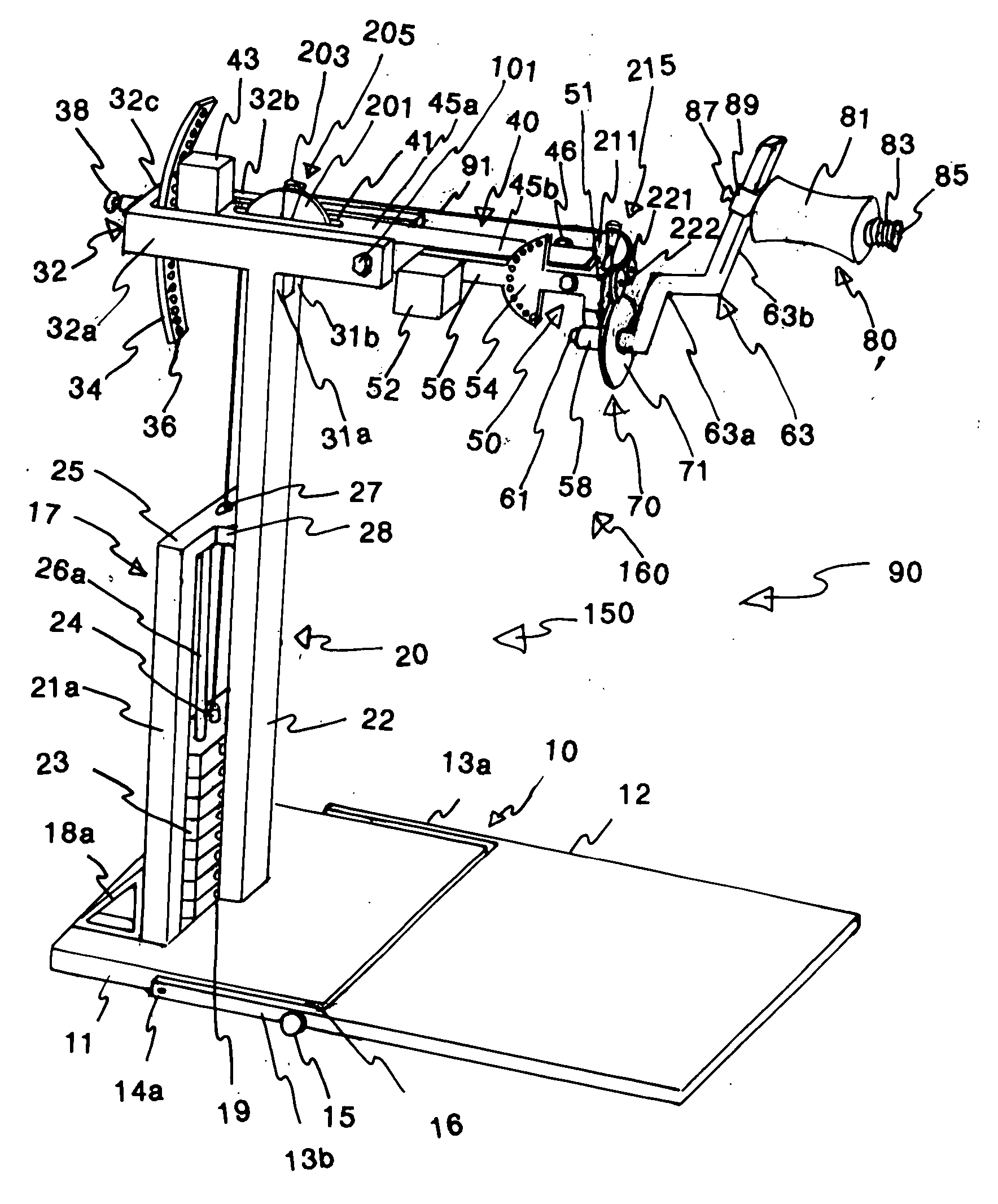
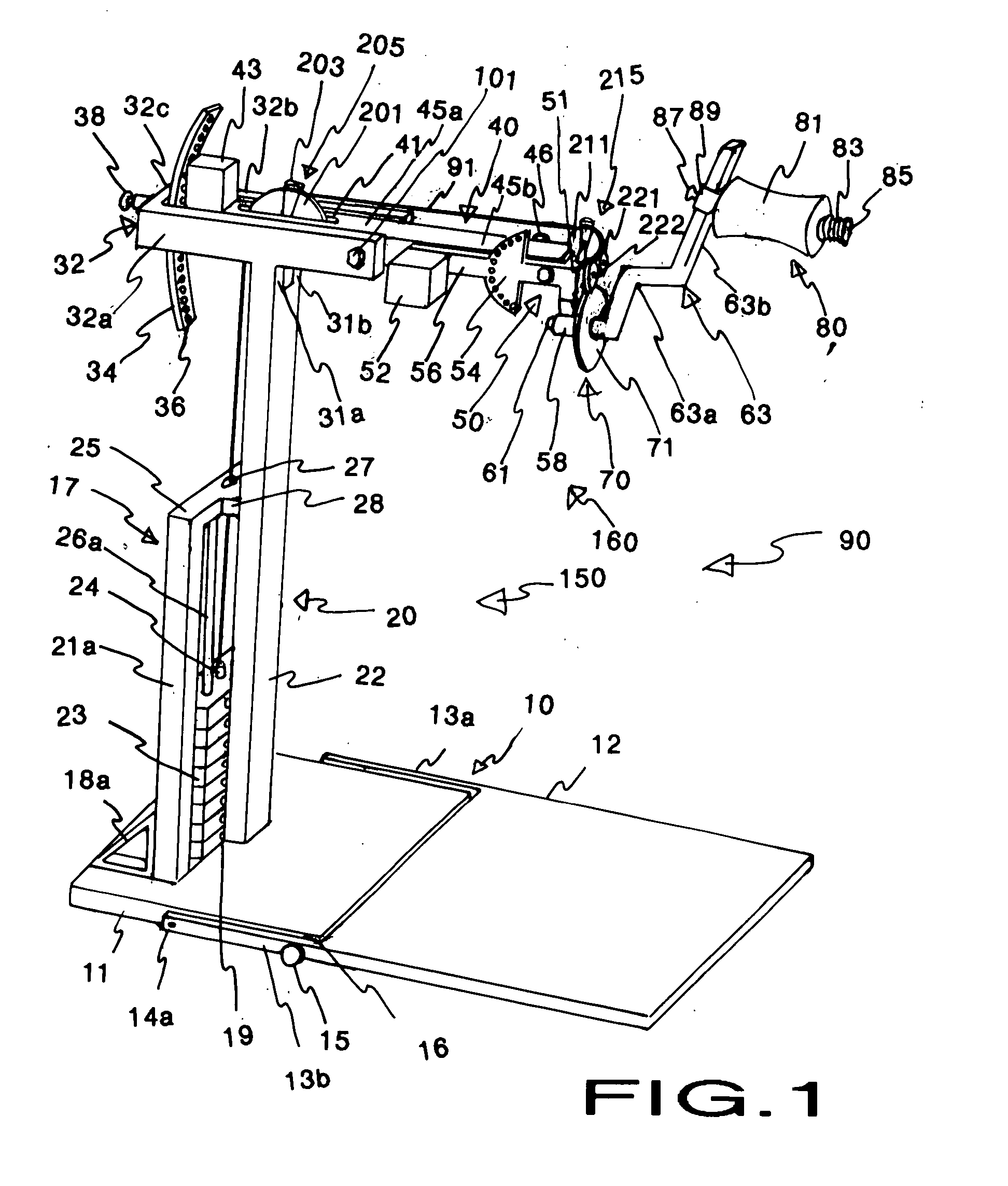
[0245] In the first embodiment, the support arm element 40, best seen in FIGS. 1,3,5 and 15, has an elongated support arm member 45 that is positioned within and extends out from the horizontal frame member 32. The approximate length of support arm member 45 is 2.5 to 4.5 feet. In FIG. 5, a threaded fulcrum bolt 101 crosses the U-opening and connects the engagement holes 108a-b on the two lateral sides 32a-b of horizontal frame member 32. The threaded fulcrum bolt 101 passes through the engagement hole 108a, a nylon thrust washer 102, a fulcrum housing 105 located at the approximate midpoint of the support arm member 45, a nylon thrust washer 106, and through the engagement hole 108b. A lock nut 107 is attached to threaded fulcrum bolt 101 to hold it in position. These components create a hinge 95 that divides support arm member 45 into a proximal support arm half 45a and a distal support arm half 45b. A nylon bushing 103 lines fulcrum housing 105 to assure smooth movement of suppor...

third embodiment

[0248] A third embodiment for support arm element 40 has the distal support arm half 45b angulated downward on proximal support arm half 45a, shown in FIGS. 15c and 16. This downward, angulation positions hinge 95 above the proximal and distal support arm halves 45a-b and makes it easier to balance support arm member 45 on fulcrum bolt 101. This enhanced balance of support arm member 45 on frame element 20 makes the apparatus 90 safer. Also note that in this embodiment, support arm member 45 is composed of two parallel beams that have one or more cross attachments (47a and 47b). The space between the parallel beams of support arm member 45 and cross attachments 47a and 47b makes up pulley opening 41. The placement of pulley unit 205 in this embodiment is in alignment with fulcrum bolt 101 (FIG. 16). Fulcrum bolt 101 acts as the axis of pulley unit 205. Also seen in FIGS. 15c and 16 is the swing plane pin 46 attached to an L-extension 481 extending laterally from the distal support a...

fourth embodiment

[0256] A fourth embodiment for swing plane adjustment element 50 (shown in FIGS. 14c and 17) has a hydraulic unit 401 originating from the distal support arm half 45b and attaching to the uppermost aspect of adjustment lever 56. This hydraulic unit 401 replaces counterweight 52 and makes it easy for the golfer to adjust the swing plane adjustment element 50 into a different swing plane angular position. This embodiment also uses a different swing plane fixation means. Instead of having the semi-circular member 54, there is a short apertured square tubing 411 and a square tube slider 412. Short apertured square tubing 411 is slidable within square tube slider 412. Short apertured square tubing 411 is attached to hinged brackets 42c on the underside of support arm member 45, and square tube slider 412 is attached to hinged brackets 413 that project down from shaft housing 58. Repositioning of swing plane adjustment element 50 by the exercising golfer causes short apertured square tubi...


PUM


Abstract

A golf swing muscle strengthener apparatus (90) for strengthening the muscles used in the downswing of the golf swing. The apparatus includes a swing plane adjustment element (50) secured at an adjustably elevated position above the ground by a frame element (20) and support arm element (40). The swing plane adjustment element (50) houses a swing arm assembly (70) adjustable to various swing plane positions. The swing arm assembly (70) is operatively coupled to a resistance means, and has a swing arm (63) shaped to circumvent the golfer's upper torso and head. The swing arm (63) exhibits pivotal rotation around a central axis of rotation and has a pad element (80) attached at its distal end for accepting the golfer's forearm. The golfer's forearm presses against the pad element (80) at the peak of the backswing, and rotates the swing arm assembly (70) during the downswing phase of the golf swing.

Description

CROSS-REFERENCE TO RELATED APPLICATIONS [0001] This application is a second continuation in part of Ser. No. 10 / 286,537 filed Nov. 2, 2002, now abandoned. The first continuation in part application is Ser. No. 11 / 004,307 filed Dec. 3, 2004. This application is also entitled to the benefit of Provisional Patent Application Ser. No. 60 / 338,051, filed Nov. 3, 2001.BACKGROUND [0002] 1. Field of Invention [0003] This invention relates to golf, specifically to a resistance exercise apparatus for strengthening the muscles used in the golf swing. [0004] 2. Discussion of Prior Art [0005] The golf swing is complex in that it requires strength but also coordinated precision and timing. The larger shoulder, torso, and back muscles initiate the club's acceleration and momentum with the downswing. As the club head approaches the ball, the number of muscles involved in the downswing increases. Specifically, the smaller forearm, wrist, and hand muscles join the larger muscles to continue the club h...

Claims


Application Information

Patent Timeline
Patent Type & Authority Applications(United States)
IPC IPC(8): A63B21/06
CPCA63B21/00072A63B69/3647A63B21/02A63B21/0611A63B21/062A63B69/3623A63B69/3641A63B69/3661A63B2208/0204A63B2210/50A63B21/1492A63B15/00A63B2225/09A63B2225/093A63B21/008A63B21/0628A63B21/4047A63B69/36212A63B69/3621A63B69/3629
Inventor BERRYMAN, THOMAS JOSEPH
Owner BERRYMAN THOMAS JOSEPH
Why Eureka
Try Eureka