Dynamically self-decaying device architecture

a device architecture and self-deceleration technology, applied in the field of processors and computer systems, can solve problems such as power dissipation and static power dissipation

Active Publication Date: 2007-07-12
ADVANCED MICRO DEVICES INC
View PDF4 Cites 19 Cited by
  • Summary
  • Abstract
  • Description
  • Claims
  • Application Information

AI Technical Summary

Problems solved by technology

Further, as gate sizes in processors and other computing devices become smaller and smaller, it is projected that static power dissipation may soon equal dynamic power dissipation.

Method used


Image

  • Dynamically self-decaying device architecture
  • Dynamically self-decaying device architecture
  • Dynamically self-decaying device architecture

Examples


Embodiment Construction

Processor Overview

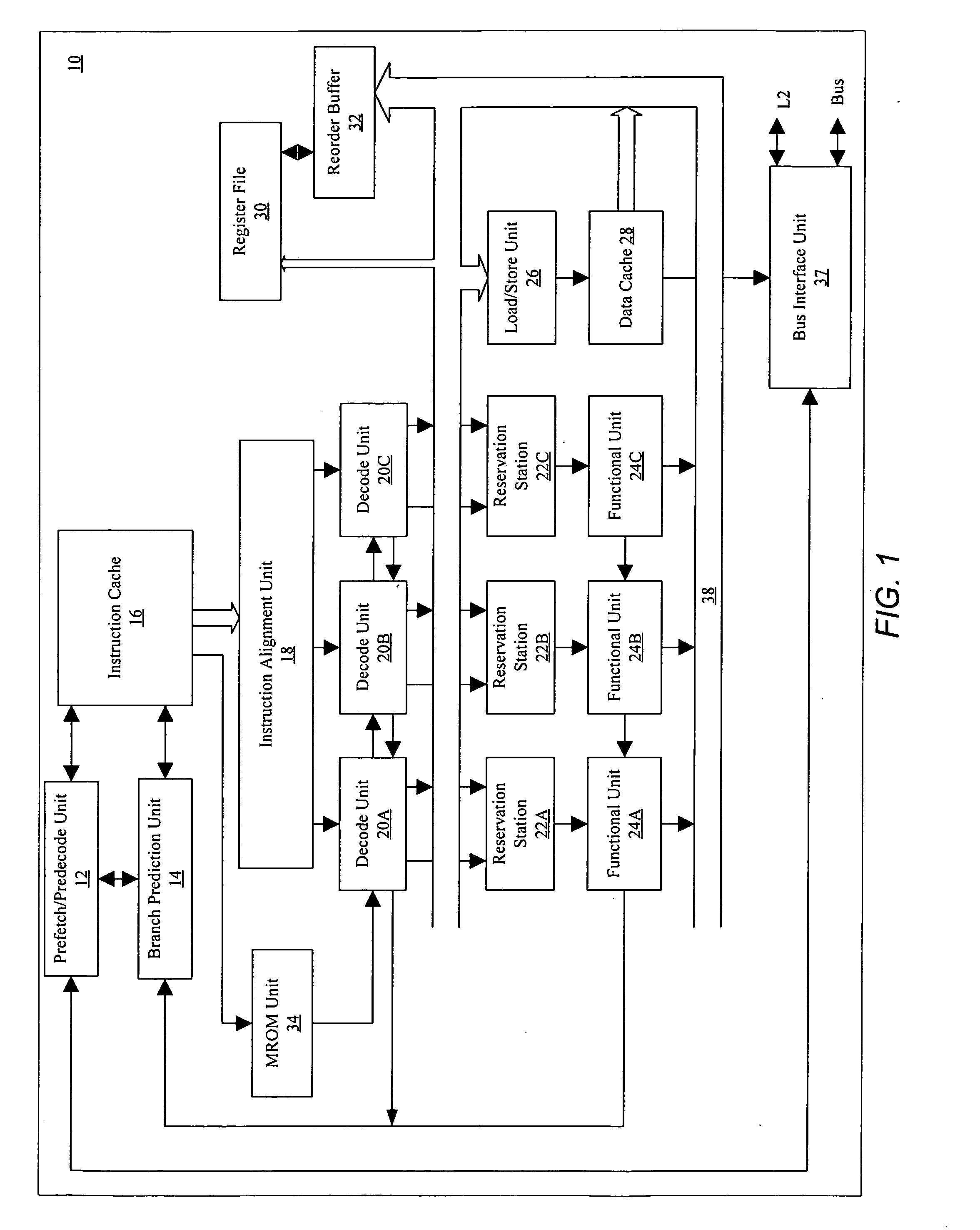
[0021] Turning now to FIG. 1, a block diagram of one embodiment of a processor 10 is shown. Other embodiments are possible and contemplated. As shown in FIG. 1, processor 10 includes a prefetch / predecode unit 12, a branch prediction unit 14, an instruction cache 16, an instruction alignment unit 18, a plurality of decode units 20A-20C, a plurality of reservation stations 22A-22C, a plurality of functional units 24A-24C, a load / store unit 26, a data cache 28, a register file 30, a reorder buffer 32, an MROM unit 34, and a bus interface unit 37. Elements referred to herein with a particular reference number followed by a letter will be collectively referred to by the reference number alone. For example, decode units 20A-20C will be collectively referred to as decode units 20.

[0022] Prefetch / predecode unit 12 is coupled to receive instructions from bus interface unit 37, and is further coupled to instruction cache 16 and branch prediction unit 14. Similarly, branch...


PUM


Abstract

A power management method and mechanism for dynamically determining which of a plurality of blocks of an electrical device may be powered on or off. A device is contemplated which includes one or more power manageable groups. A power management unit associated with the apparatus is configured to detect instructions which are scheduled for execution, identify particular power group(s) which may be required for execution of the instruction, and convey an indication which prevents the particular power group(s) from entering a powered off state, in response to detecting said instruction. If the power management unit does not detect an incoming or pending instructions, for a predetermined period of time, which requires a particular power group(s) for execution, the power management unit may convey an indication which causes or permits the corresponding power group(s) to enter a powered off state. A power group may automatically decay to a powered off state in the absence of a detected instruction requiring the power group. Instructions may be encoded to identify required power groups.

Description

BACKGROUND OF THE INVENTION [0001] 1. Field of the Invention [0002] This invention is related to the field of processors and computer systems and, more particularly, to power management in processors and other devices. [0003] 2. Description of the Related Art [0004] While processing performance in computing and other devices has garnered much attention, the topic of power dissipation has become increasingly important. Generally speaking, the public has come to expect their computing devices to be smaller and more mobile. Whether the device is a portable computer, cell phone, personal digital assistant (PDA), or otherwise, portable power sources such as batteries are becoming commonplace. Given that such power supplies are limited in nature, it is extremely important that the power which is available be used in an efficient manner. Consequently, power management techniques in such devices are becoming more widespread. Further, as gate sizes in processors and other computing devices b...

Claims


Application Information

Patent Timeline
Patent Type & Authority Applications(United States)
IPC IPC(8): G06F1/32
CPCG06F9/3855G06F1/3228G06F9/3836G06F1/3287Y02B60/1278G06F1/3203G06F9/384G06F9/3885Y02B60/32G06F9/30149Y02B60/1282G06F9/30145G06F9/3869Y02D10/00Y02D30/50G06F9/3856G06F1/26G06F1/32
Inventor RAGHUVANSHI, PREETHAM
Owner ADVANCED MICRO DEVICES INC
Why Eureka
Try Eureka