Mechanisms to avoid inefficient core hopping and provide hardware assisted low-power state selection

a technology of low-power state selection and core hopping, applied in the direction of instruments, computation using denominational number representation, register arrangements, etc., can solve the problems of inability to intelligently choose when to core hop, inability to optimize processor operation, and increased thermal density and leakage power,

Inactive Publication Date: 2011-06-30
INTEL CORP
View PDF2 Cites 76 Cited by
  • Summary
  • Abstract
  • Description
  • Claims
  • Application Information

AI Technical Summary

Problems solved by technology

However, as a corollary to the increased processing power, the problems with thermal density and leakage power are also amplified.
However, inherent with moving entire context from one core to another is the cost—wasted execution cycles, energy spent on the move, and cold caches.
Yet, currently there is no intelligent decision on when to core hop outside of the initial core hop decision based on thermal density.
As a result, a core hop may be initiated when a core hop is not needed—a triggering, thermal-density condition may be self-alleviating—or may be infeasible—the hop results in the same or worse thermal conditions.
Currently, today's privileged level software—Operating Systems—are not extremely accurate in requesting transition to low power states.
As a result, previous software may request a core to enter a specific low power state that is inefficient either from being too deep—lower power consumed but not sufficient wake time in comparison to the amount of time the core is going to be idle in the future—or to shallow—more power consumed when the amount of idle time is greater than the wake time.

Method used


Image

  • Mechanisms to avoid inefficient core hopping and provide hardware assisted low-power state selection
  • Mechanisms to avoid inefficient core hopping and provide hardware assisted low-power state selection
  • Mechanisms to avoid inefficient core hopping and provide hardware assisted low-power state selection

Examples


Embodiment Construction

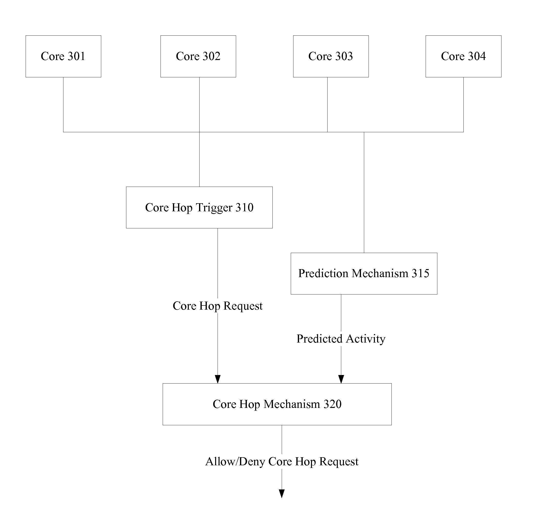
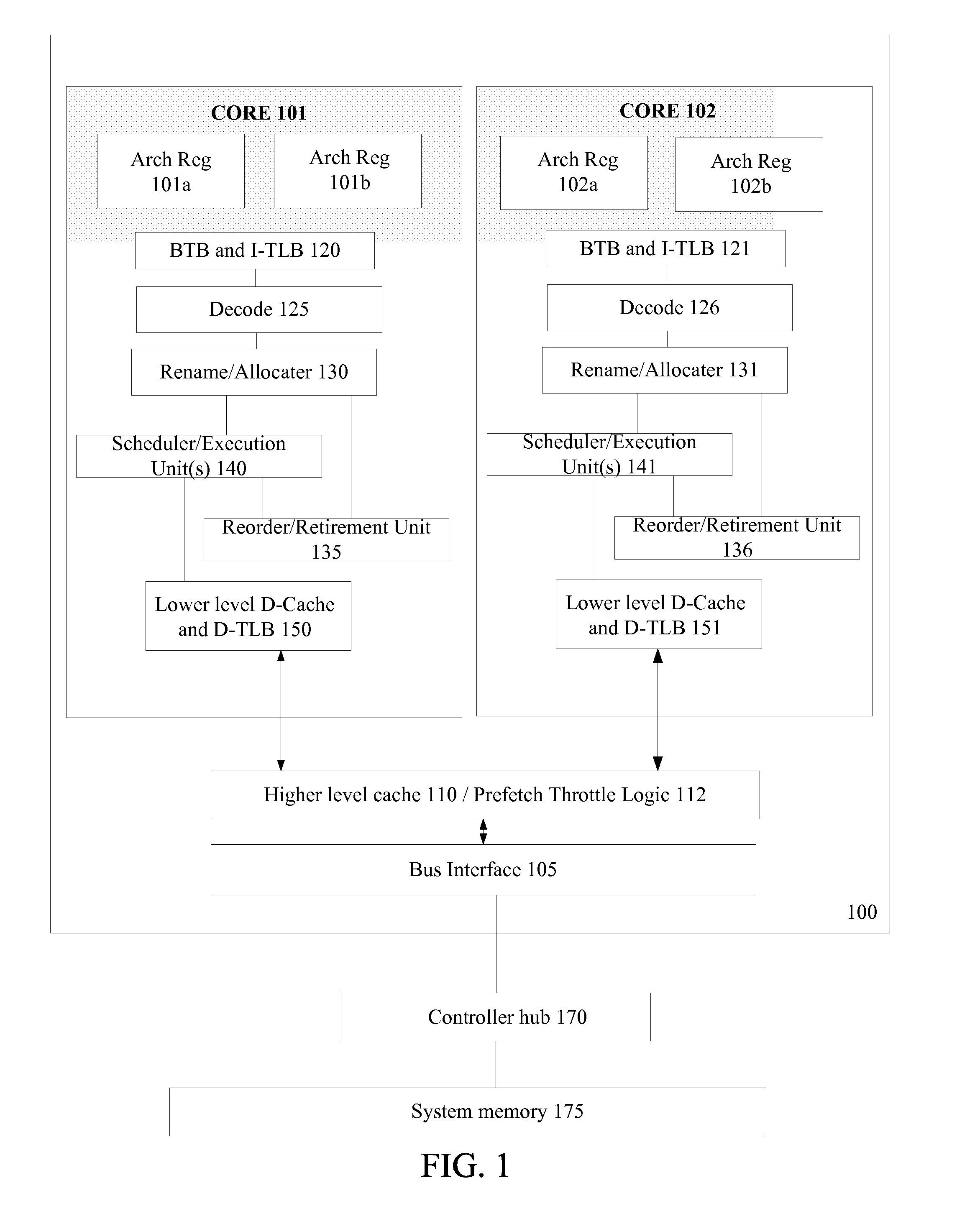
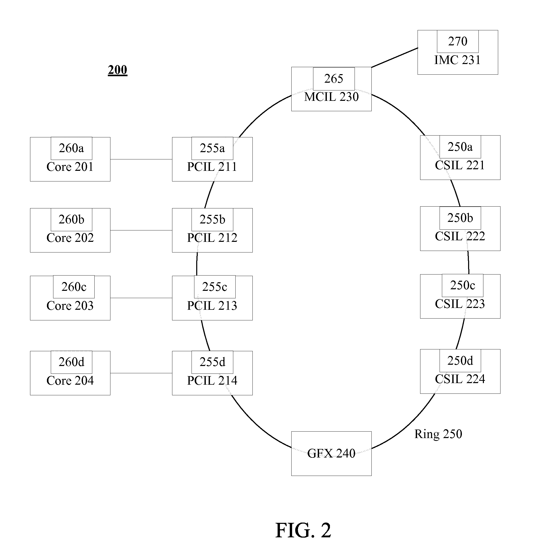
[0016]In the following description, numerous specific details are set forth such as examples of specific hardware structures / mechanisms for idle-activity prediction, idle duration measurement, accuracy determination; specific processor configurations, specific core hop conditions, specific low power states, specific processor units / logic, specific examples of processing elements etc. in order to provide a thorough understanding of the present invention. It will be apparent, however, to one skilled in the art that these specific details need not be employed to practice the present invention. In other instances, well known components or methods, such as specific and alternative multi-core and multi-threaded processor architectures, specific logic circuits for illustrated modules / blocks, and specific operational details of microprocessors, have not been described in detail in order to avoid unnecessarily obscuring the present invention.

[0017]The method and apparatus described herein ar...


PUM


Abstract

An apparatus and method is described herein for avoiding inefficient core hopping and providing hardware assisted power state selection. Future idle-activity of cores is predicted. If the residency of activity patterns for efficient core hop scenarios is predicted to be large enough, a core is determined to be efficient and allowed. However, if efficient activity patterns are not predicted to be resident for long enough—inefficient patterns are instead predicted to be resident for longer—then a core hop request is denied. As a result, designers may implement a policy for avoiding core hops that weighs the potential gain of the core hop, such as alleviation of a core hop condition, against a penalty for performing the core hop, such as a temporal penalty for the core hop. Separately, idle durations associated with hardware power states for cores may be predicted in hardware. Furthermore, accuracy of the idle duration prediction is determined. Upon receipt of a request for a core to enter a power state, a power management unit may select either the hardware predicted power state, if the accuracy is high enough, or utilize the requested power state, if the accuracy of the hardware prediction is not high enough.

Description

FIELD[0001]This invention relates to the field of processor execution and, in particular, to optimizing processor operation.BACKGROUND[0002]Advances in semi-conductor processing and logic design have permitted an increase in the amount of logic that may be present on integrated circuit devices. As a result, computer system configurations have evolved from a single or multiple integrated circuits in a system to multiple processor dice, multiple cores, multiple hardware threads, and multiple logical processors present on individual integrated circuits. A processor or integrated circuit typically comprises a single physical processor die, where the processor die may include any number of cores, hardware threads, or logical processors.[0003]The ever increasing number of processing elements—cores, hardware threads, and logical processors—on integrated circuits enables more tasks to be accomplished in parallel. However, as a corollary to the increased processing power, the problems with t...

Claims


Application Information

Patent Timeline
Patent Type & Authority Applications(United States)
IPC IPC(8): G06F15/76G06F9/30G06F9/06G06F12/00
CPCG06F1/3203Y02B60/142G06F9/5094G06F9/30058G06F9/30094G06F9/30098Y02D10/00
Inventor SONG, JUSTIN J.CRAWFORD, JOHN H.
Owner INTEL CORP
Why Eureka
Try Eureka