Multi-voltage multi-battery power management unit

a power management unit and multi-battery technology, applied in the direction of power supply for data processing, instruments, measurement devices, etc., can solve problems such as energy-inefficient power supply operation

Inactive Publication Date: 2005-12-29
AVAGO TECH INT SALES PTE LTD
View PDF30 Cites 83 Cited by
  • Summary
  • Abstract
  • Description
  • Claims
  • Application Information

AI Technical Summary

Benefits of technology

[0008] A system and method for implementing a multi-voltage multi-battery power management integrated circuit, substantially as shown in and/or described in connection with at least one of the figures, as set forth more comple

Problems solved by technology

Converting an input voltage to a regulated output voltage, particularly where there is a substantial disparity be

Method used


Image

  • Multi-voltage multi-battery power management unit
  • Multi-voltage multi-battery power management unit
  • Multi-voltage multi-battery power management unit

Examples


Embodiment Construction

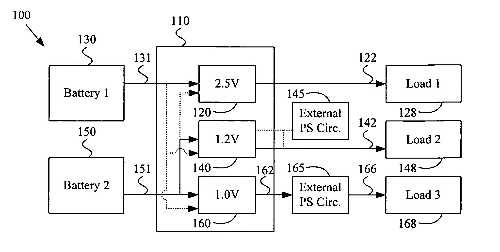
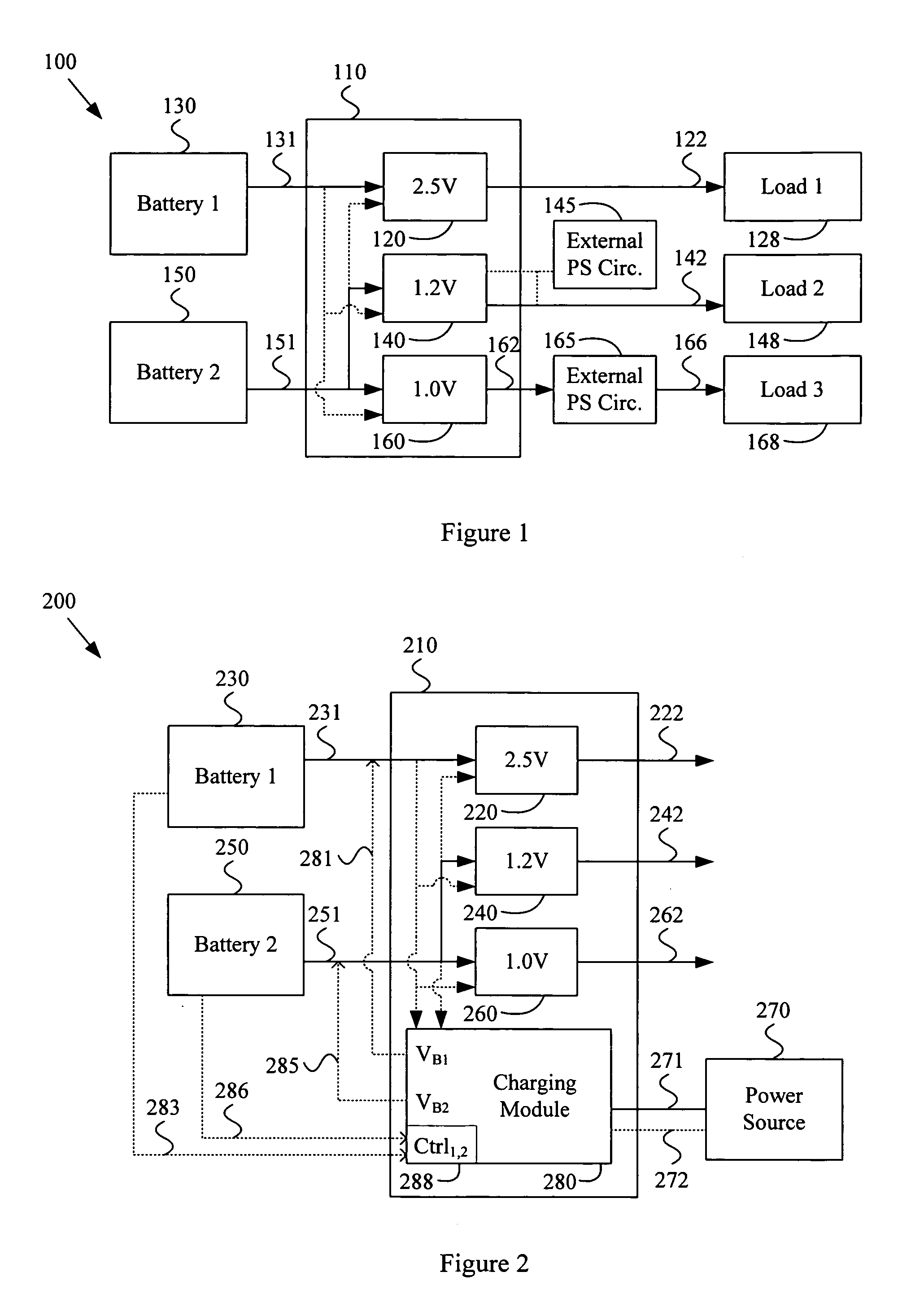
[0014]FIG. 1 illustrates an exemplary multi-battery system 100 comprising a power management integrated circuit 110, in accordance with various aspects of the present invention. The system 100 may comprise any of a large variety of system characteristics. For example and without limitation, the system 100 may comprise characteristics of a portable communication system (e.g., a portable phone or portable e-mail device), a portable computing device, a portable media playing device, etc. Accordingly, the scope of various aspects of the present invention should not be limited by characteristics of a particular multi-battery system.

[0015] The following discussion may generally refer to one or more “modules” that perform various functions. It should be noted that a “module” may be implemented in hardware, software or a combination thereof. Further, portions of modules may be shared. For example, a first module may share various hardware and / or software components with a second module. Ac...


PUM


Abstract

A system and method for implementing a multi-voltage multi-battery power management integrated circuit. Various aspects of the present invention provide a power management integrated circuit. The power management IC may comprise a first regulator module that receives a first battery power signal from a first battery characterized by a first battery voltage and outputs a first regulated power signal, based at least in part on the first battery power signal. The power management IC may also comprise a second regulator module that receives a second battery power signal from a second battery characterized by a second battery voltage and outputs a second regulated power signal, based at least in part on the second battery power signal. The second battery voltage may, for example, be substantially different than the first battery voltage. The power first and second regulated power signals may, for example, correspond to substantially different power supply voltages.

Description

CROSS-REFERENCE TO RELATED APPLICATIONS / INCORPORATION BY REFERENCE [0001] This patent application is related to and claims priority from provisional patent application Ser. No. 60 / 583,996, filed Jun. 29, 2004, and entitled “MULTI-VOLTAGE MULTI-BATTERY POWER MANAGEMENT UNIT,” the contents of which are hereby incorporated herein by reference in their entirety.FEDERALLY SPONSORED RESEARCH OR DEVELOPMENT [0002] [Not Applicable]SEQUENCE LISTING [0003] [Not Applicable]MICROFICHE / COPYRIGHT REFERENCE [0004] [Not Applicable]BACKGROUND OF THE INVENTION [0005] Various components of electrical systems may utilize power at multiple voltage levels. Power management circuitry may, for example, receive power from a battery, or a plurality of batteries at a common voltage, and provide regulated output power to various system components. A power management unit may, for example, utilize a power regulator integrated circuit to regulate the output power. Such a power regulator integrated circuit may, f...

Claims


Application Information

Patent Timeline
IPC IPC(8): G06F1/26
CPCG06F1/26
Inventor RANGANATHAN, SUMANTVORENKAMP, PIETERKIM, NEIL Y.CHEN, CHUN-YING
Owner AVAGO TECH INT SALES PTE LTD
Why Eureka
Try Eureka