
Method and device for controlling the passage of radiant energy into architectural structures

Inactive Publication Date: 2007-07-19
CPI DAYLIGHTING
View PDF36 Cites 38 Cited by
  • Summary
  • Abstract
  • Description
  • Claims
  • Application Information

AI Technical Summary

Benefits of technology

[0003] The invention is an assembly for controlling the passage of radiant energy through a defined region. It includes at least two control members positioned across the defined region and mounted for generally parallel movement relative to each other between a closed position and an open position. The defined region may be, for example, a portion or the entirety of a skylight, a roof or a wall.
[0004] The control members each have a plurality of transmitting areas and blocking areas. When two control members are used, the respective transmitting areas and blocking areas of the first and second control members are sized, shaped and positioned so that the transmitting areas of the first control member are aligned with the blocking areas of

Problems solved by technology

Prior approaches to controlling the level of solar radiation passing into architectural structures have been unduly complex and expensive, and of only limited usefulness.
Furthermore, louver blinds cannot achieve complete light block-out, are difficult and expensive to assemble, apply, operate, maintain and replace, and cannot be readily adapted for use in non-vertical applications or in large glazed roofing areas.

Method used


Image

  • Method and device for controlling the passage of radiant energy into architectural structures
  • Method and device for controlling the passage of radiant energy into architectural structures
  • Method and device for controlling the passage of radiant energy into architectural structures

Examples


Embodiment Construction

[0034] The following examples further illustrate the invention but should not be construed as in any way limiting its scope.

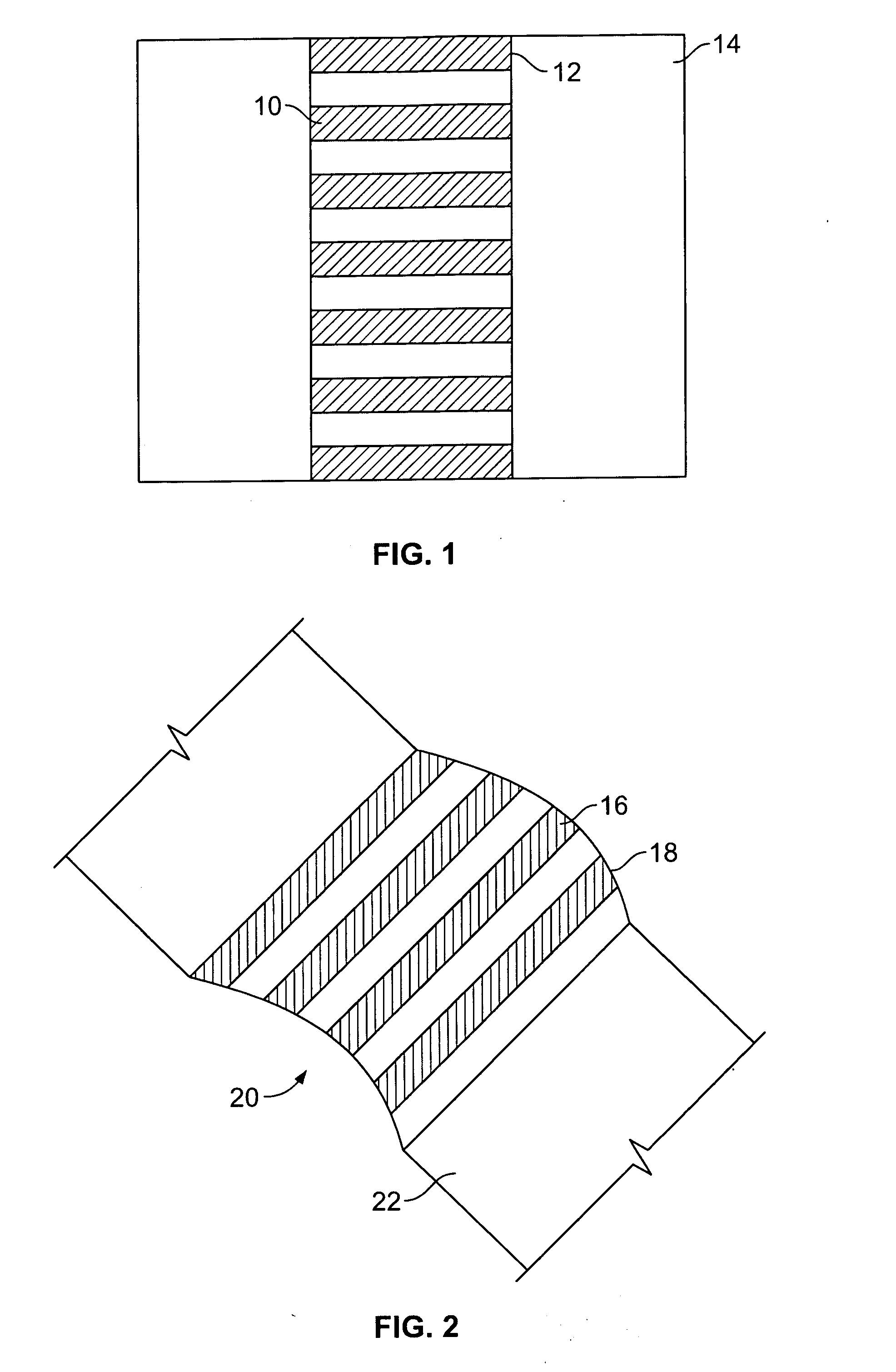
[0035] In one embodiment of the invention, as illustrated in FIG. 1, a control assembly 10 is shown mounted in a defined region 12 in a roof 14 to control the passage of radiant energy through the defined region. Although this embodiment illustrates the mounting of the control assembly across a generally planar defined region, a curved control assembly 16 may also be mounted across a curved defined region 18, such as the curved skylight 20 of roof 22 as illustrated in FIG. 2.

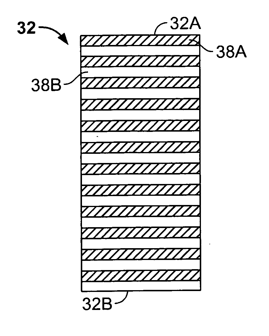
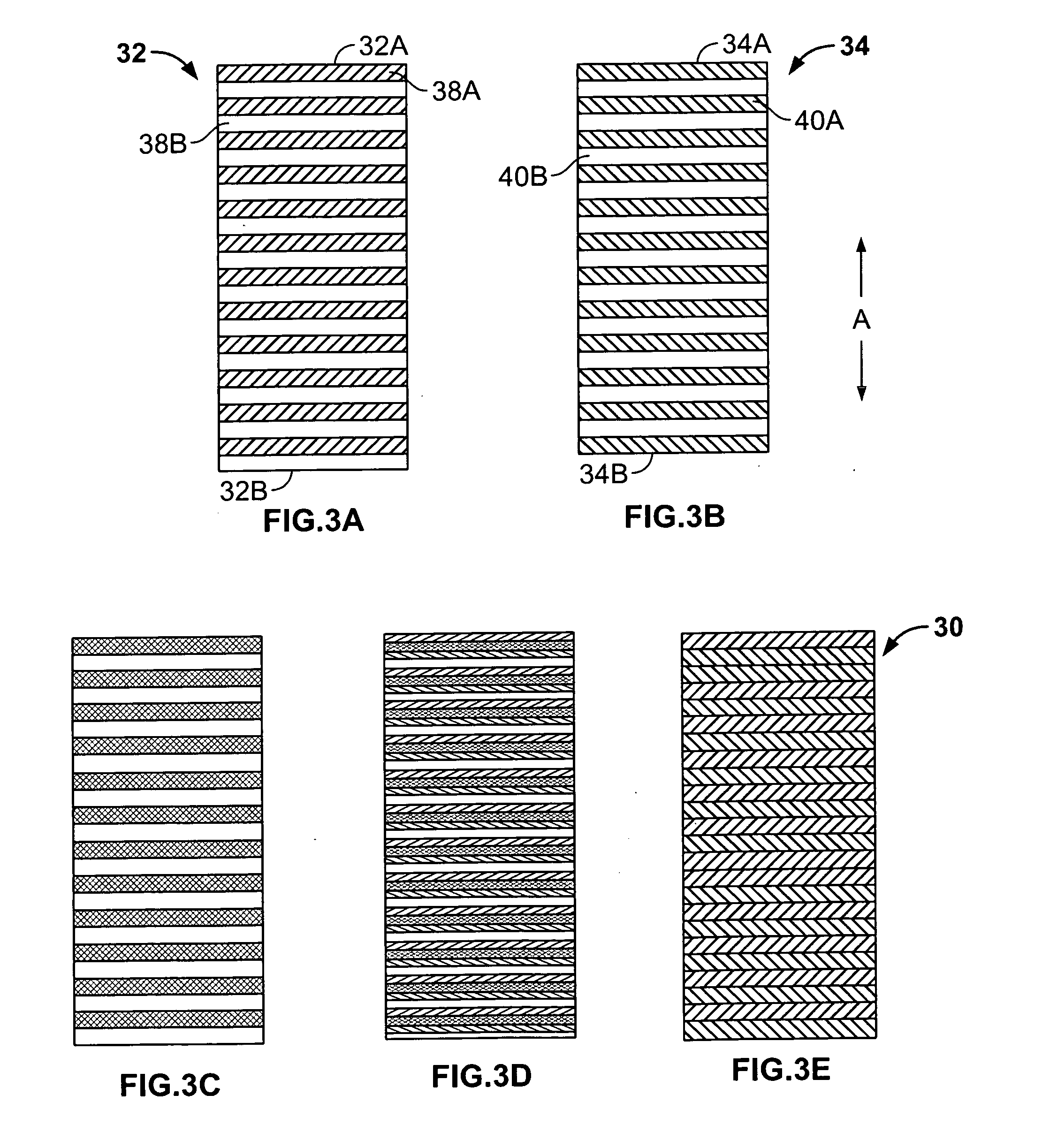
[0036] Turning now to FIGS. 3A-3E, on assembly 30 in accordance with the invention is illustrated in an embodiment including two control members in the form of planar rigid rectangular panels 32 and 34 of generally the same shape and dimensions. These panels are mounted for generally parallel movement relative to each other (in direction A) between a fully closed position (FIG. 3E) and a ...


PUM


Abstract

An assembly for controlling the passage of radiant energy through a skylight, a roof or a wall including at least two linked control members positioned across the defined region mounted for generally parallel linked movement relative to each other between a closed position and an open position. The control members have a plurality of transmitting areas and blocking areas arranged so that the respective transmitting areas and blocking areas of the control members are aligned when the members are in the closed position and the transmitting areas of the first control member are aligned with the transmitting areas of the second control member when the panels are in the open position. A motorized motion unit may be used for producing relative movement between the control members. The assembly is particularly well-adapted to be used with a series of adjacent dual panel glazing units where assemblies associated with each adjacent dual panel glazing unit are linked to and controlled by a single motion control device.

Description

FIELD OF THE INVENTION [0001] This invention pertains to devices for controlling the passage of radiant energy into architectural structures and, more particularly, to systems using two or more generally parallel members for controlling the passage of radiant energy through a defined region and into an architectural structure. BACKGROUND OF THE INVENTION [0002] Prior approaches to controlling the level of solar radiation passing into architectural structures have been unduly complex and expensive, and of only limited usefulness. For example, louver blind assemblies using pivoting flexible members operable within a double-glazed window unit have been suggested for this purpose. Such louver blinds require substantial support of the flexible members which, additionally, are typically controlled from both their distal and their proximal ends. Furthermore, louver blinds cannot achieve complete light block-out, are difficult and expensive to assemble, apply, operate, maintain and replace,...

Claims


Application Information

Patent Timeline
IPC IPC(8): A47H23/00
CPCA47H23/06E06B9/386E04D3/06E04C2/543
Inventor KONSTANTIN, MOSHEKONSTANTINO, EITAN
Owner CPI DAYLIGHTING
Learn More