Oil strainer

a strainer and oil technology, applied in the direction of moving filter elements, filtering process, filtration separation, etc., can solve the problems of poor weld quality, troublesome positioning work, damaged filter elements, etc., and achieves less prone to deformation, high rigidity, and high rigidity.

Inactive Publication Date: 2007-07-19
TOYO ROKI MFG CO LTD
View PDF4 Cites 6 Cited by
  • Summary
  • Abstract
  • Description
  • Claims
  • Application Information

AI Technical Summary

Benefits of technology

[0026]Also, since the peripheral edge portion of the open portion formed on the case body is formed in a state of being closed throughout the entire periphery, the rigidity of the case body can be kept high. Because of the high rigidity, when the cover body is welded to the case body to assemble the oil strainer, deformation is less liable to occur. Thereby, an oil strainer with high accuracy can be formed. Also, because deformation is less liable to occur, measures against deformation need not be taken specially in the welding process, and welding work can be performed easily.
[0027]Also, after the case body and the cover body have been welded to each other, an airtightness test is conducted to check whether or not any poor weld is present. According to the present invention, the process of the airtightness test can be simplified, and the test accuracy can be increased. That is to say, the airtightness test is conducted by hermetically sealing the inflow portion and the outflow portion and by causing air to flow from either of the inflow portion and the outflow portion. In this case, the air inflow portion must be sealed. However, since the open portion is independent of the in flow portion and the out flow portion, the sealing condition does not exert an influence on the weld portion. Therefore, the presence of defect can be checked quickly. Even if a defect is present, the position of defect can be determined easily.

Problems solved by technology

However, of the oil strainers disclosed in Patent Document 1, an oil strainer of a type in which the filter element is inserted has a disadvantage that the filter element may be damaged in the insertion process, and also the work for positioning the filter element is troublesome.
Also, in the oil strainer of a type in which the filter element is held between the two components, poor weld may occur unless the joint portion of the components is fabricated into a special shape in advance.
Further, in the oil strainer in which the filter element and one component are formed integrally, when the component formed integrally with the filter element is joined to the open portion formed in the tubular component, it is difficult to check whether the tip end of the filter element engages surely with the locking portion of the tubular component, so that it is difficult to perform the positioning work efficiently.
In the case where the housing is formed by a plurality of components and is formed by welding these components, it is very difficult to perform vibration welding unless the strength or rigidity of the component is made high in advance.

Method used


Image

  • Oil strainer
  • Oil strainer
  • Oil strainer

Examples


first embodiment

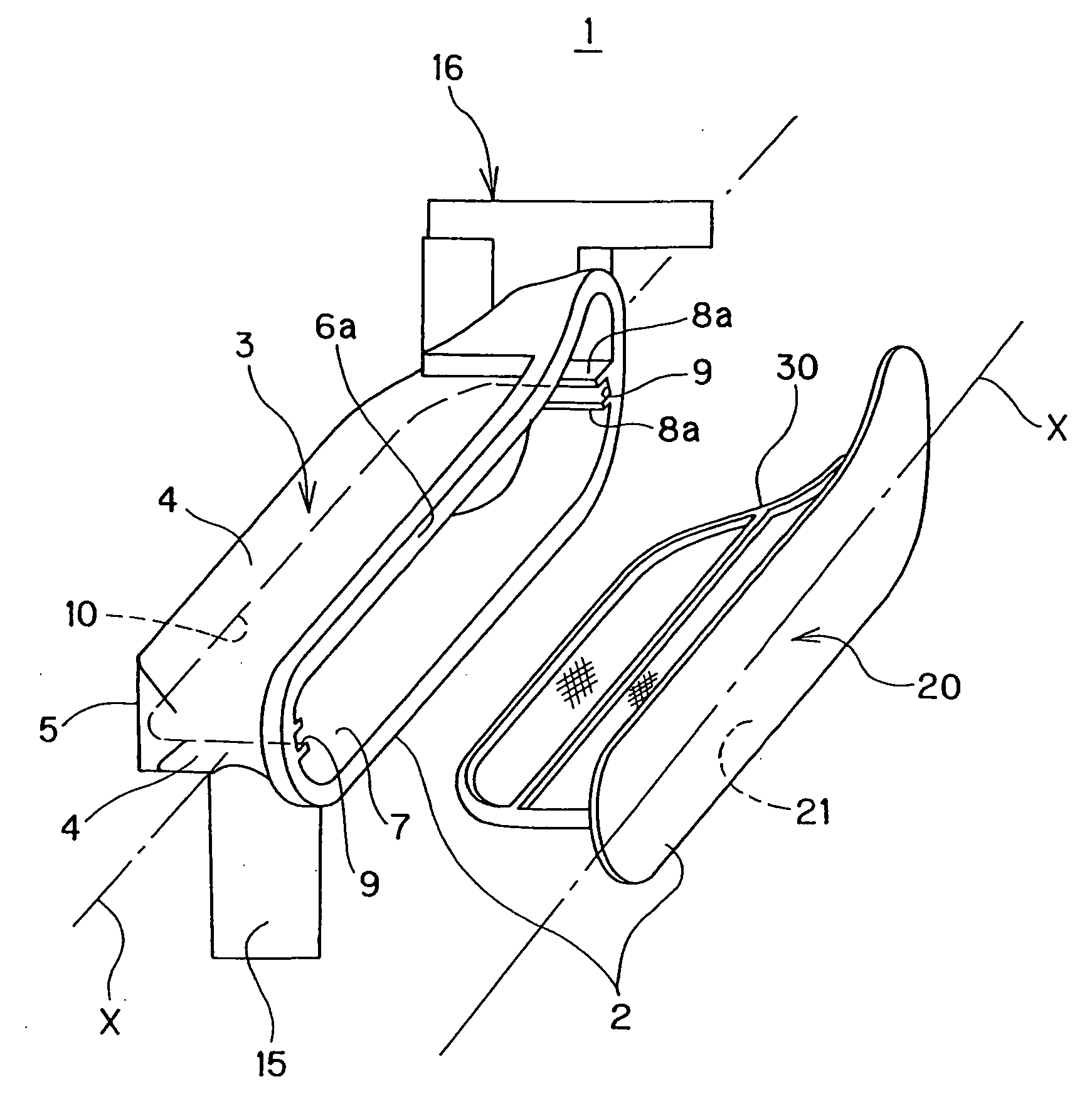
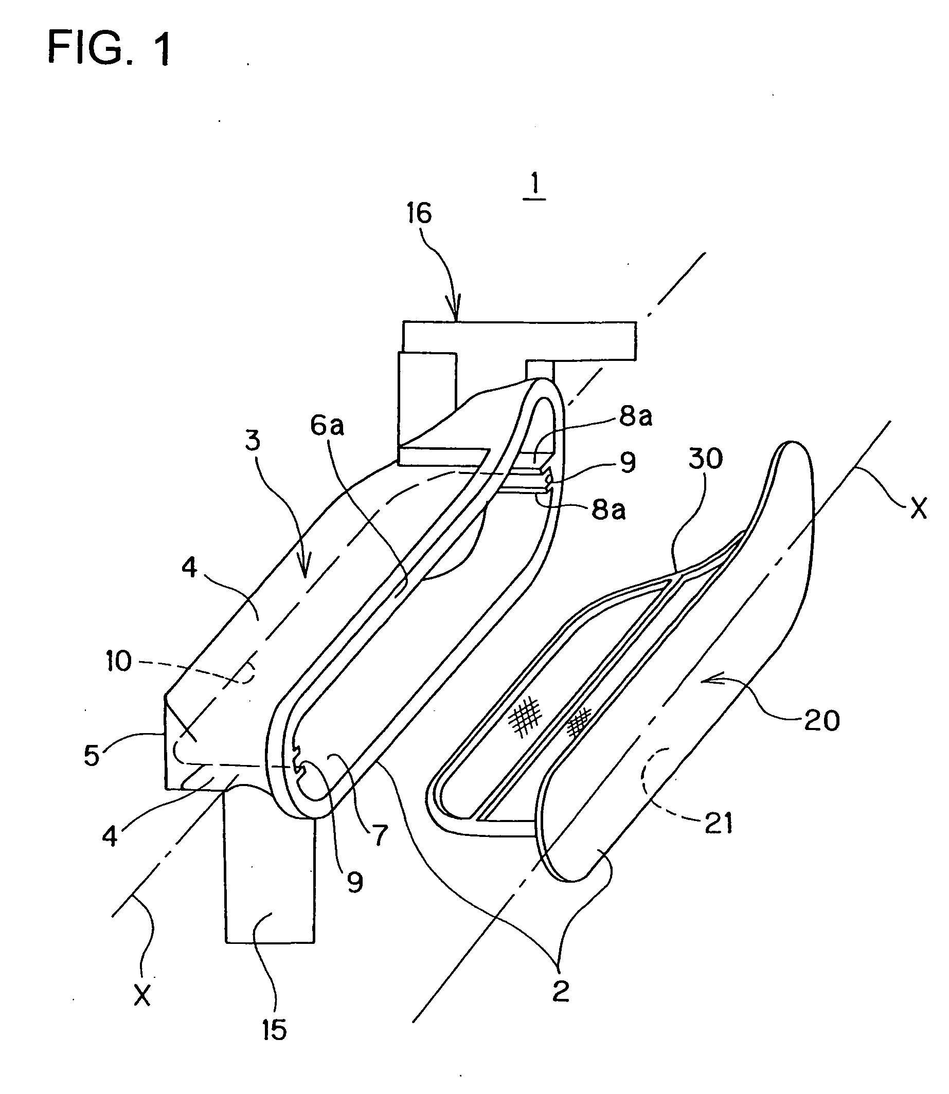
[0039]FIGS. 1 to 6 show an oil strainer 1 in accordance with the present invention.

[0040]The oil strainer 1 includes a housing 2 that forms the outer shell of the oil strainer 1 and allows oil to flow therein and a filter element 30 disposed within the housing 2. The housing 2 is made up of a case body 3 formed of a resin material and a cover body 20 formed of a resin material. Also, the filter element 30 and the cover body 20 are formed as one member.

[0041]The case body 3 includes a side wall portion 4 and a bottom surface portion 5, and an open portion 6 is formed at the upper part of the case body 3. Also, the case body 3 is formed slenderly so as to extend in one axis direction X. The upper open portion 6 is formed so as to extend in one axis direction X corresponding to the shape of the case body 3.

[0042]Also, on the first end side in one axis direction X of the case body 3, an inflow portion 15 through which oil flows in is provided so as to project from the side wall portion ...

second embodiment

[0055]Next, an oil strainer 50 in accordance with the present invention is described with reference to FIG. 7.

[0056]In the oil strainer 50, a housing 51 forming the outer shell of the oil strainer 50 is made up of a case body 3 and a cover body 55, and the cover body 55 and a filter element 60 are formed as separate members. The construction of the case body 3 is the same as that of the case body 3 in accordance with the first embodiment. Herein, the same symbols are applied to the elements of the case body 3 that are equivalent to those in the first embodiment, and the explanation thereof is omitted.

[0057]The cover body 55 is formed into a plate shape, and on the inner surface 56 side thereof, a groove portion 57 is formed in the center in the width direction thereof. The groove portion 57 extends along the above-described one axis direction X in which the housing 51 extends, and is formed so as to connect both end portions in one axis direction X of the cover body 55 to each other...

third embodiment

[0061]Next, a third embodiment is described with reference to FIGS. 8 to 10.

[0062]An oil strainer 70 in accordance with the third embodiment also includes a housing 71 forming the outer shell of the oil strainer 70 and a filter element 100 disposed within the housing 71. The housing 71 is made up of a case body 72 formed with an open portion 85 and a cover body 90 for closing the open portion 85. This oil strainer 70 is also formed slenderly so as to extend in one axis direction X.

[0063]The case body 72 is made up of a peripheral wall portion 76 and a top surface portion 77, and the open portion 85 is formed on the bottom surface thereof. The first end side in one axis direction X is closed by the peripheral wall portion 76, and on the other hand, the second end side is provided with an outflow portion 73 for allowing oil having passed through the housing 71 and having been filtered to flow out. Also, in the case body 72, partition portions 78 and 79 projecting from one side surface...


PUM

PropertyMeasurementUnit
dimensionaaaaaaaaaa
right anglesaaaaaaaaaa
shapeaaaaaaaaaa

Abstract

There is provided an oil strainer in which the assembling work can be performed very easily, and more over high quality can be ensured. An oil strainer 1 includes a housing 2 formed by closing an open portion 6 of a case body 3 by a cover body 20 and a filter element 30 disposed in the housing 2. In the case body 3, there is provided a groove portion 8 including a guide portion 9 for guiding the filter element 30 to the inside of the case body 3 by inserting both side edges of the filter element 30 into the inside and a locking portion 10 for locking the filter element 30 by inserting the tip end edge in the insertion direction of the filter element 30 into the inside.

Description

BACKGROUND OF THE INVENTION[0001]1. Field of the Invention[0002]The present invention relates to an oil strainer that is used for vehicles and industrial machinery to filter oil.[0003]2. Description of the Related Art[0004]An oil strainer is generally made up of a housing for allowing oil to flow therein and a filter element disposed in the housing. An oil strainer of a type in which the housing is formed of a resin material is widely known. In the case where the housing is formed of a resin material, the oil strainer is completed mainly by molding a plurality of components in advance and by setting a filter element between these components and welding the components to each other.[0005]Patent Document 1 discloses one example of the conventional oil strainer. In this oil strainer, a pipe-form housing is formed by two resin-made components. At both ends in the axial direction of the housing, an inflow portion for allowing oil to be filtered to flow and an outflow portion for discharg...

Claims


Application Information

Patent Timeline
Patent Type & Authority Applications(United States)
IPC IPC(8): B01D35/00
CPCB01D27/005B01D29/012B01D29/01
Inventor SATO, TAISUKE
Owner TOYO ROKI MFG CO LTD
Why Eureka
Try Eureka