Large depth of field line scan camera

a scanning camera and depth of field technology, applied in the direction of instruments, measurement devices, electric discharge tubes, etc., can solve the problems of requiring mechanical focusing apparatus, focusing parts are subject to higher wear and maintenance requirements, and focusing apparatus tends to be the limiting factor in the speed of scanning system operation

Inactive Publication Date: 2007-07-19
ACCU SORT SYST
View PDF23 Cites 41 Cited by
  • Summary
  • Abstract
  • Description
  • Claims
  • Application Information

AI Technical Summary

Benefits of technology

[0010] In another preferred embodiment, a system for imaging an object comprises a surface for receiving an object to be imaged and an imaging device comprising a housing, a plurality of independent linear imaging sensors positioned in the housing so that a face of each of the plurality of independent linear imaging sensors is parallel to the surface, where the plurality of independent linear imaging sensors is adapted to receive reflected light from the object on the surface, a fixed focusing optical device mounted to the housing and comprising a single lens for focusing the reflected light from the object on the surface onto each of the plurality of independent linear imaging sensors, and a processor coupled to the plurality of independent linear imaging sensors for reading an output signal from each of the plurality of independent linear imaging sensors. The single lens may be an irregular lens that provides a plurality of focal lengths each corresponding to a respective one of the plurality of independent linear imaging sensors. The system may also comprise a plurality of linear actuators for independently moving each of the plurality of independent linear imaging sensors with respect to the fixed focusing optical device. In addition to the linear actuators, a height measuring device may be used for detecting a height of the object on the surface prior to reaching the imaging device, wherein the detected height is used by each of the plurality of linear actuators for moving each of the plurality of independent linear imaging sensors with respect to the fixed focusing device. A feedback loop from the processor to each of the plurality of linear actuators may be used to assist in positioning each of the plurality of independent linear imaging sensors.

Problems solved by technology

One disadvantage with prior known CMOS- and CCD-based scanning systems is that they require a mechanical focusing apparatus in order to focus the light reflected from the coded symbology onto the image sensor.
Since a mechanical focusing apparatus typically operates slower than the image sensor and other electronics within the scanner, the focusing apparatus tends to be the limiting factor in the speed of operation of the scanning system.
Additionally, focusing parts are subject to higher wear and maintenance requirements.
Although there are scanning systems that are available which do not require a moveable focusing apparatus, these scanning systems typically have a very small depth of field.
While the system described in U.S. Pat. No. 6,783,068 is effective for scanning a large depth of field, suitable area array sensors are currently available only at a very high cost.
Further, such sensors typically transmit large quantities of information that can burden internal or external processing systems.

Method used


Image

  • Large depth of field line scan camera
  • Large depth of field line scan camera
  • Large depth of field line scan camera

Examples


Embodiment Construction

)

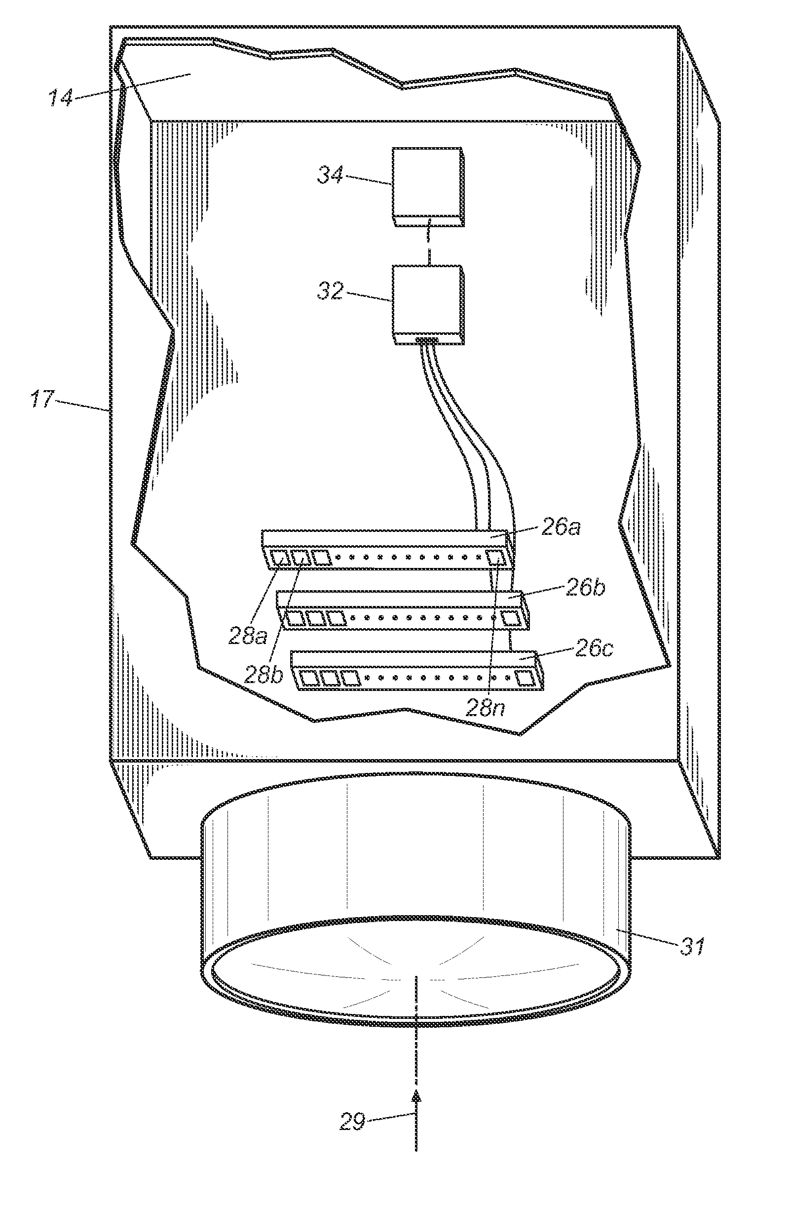
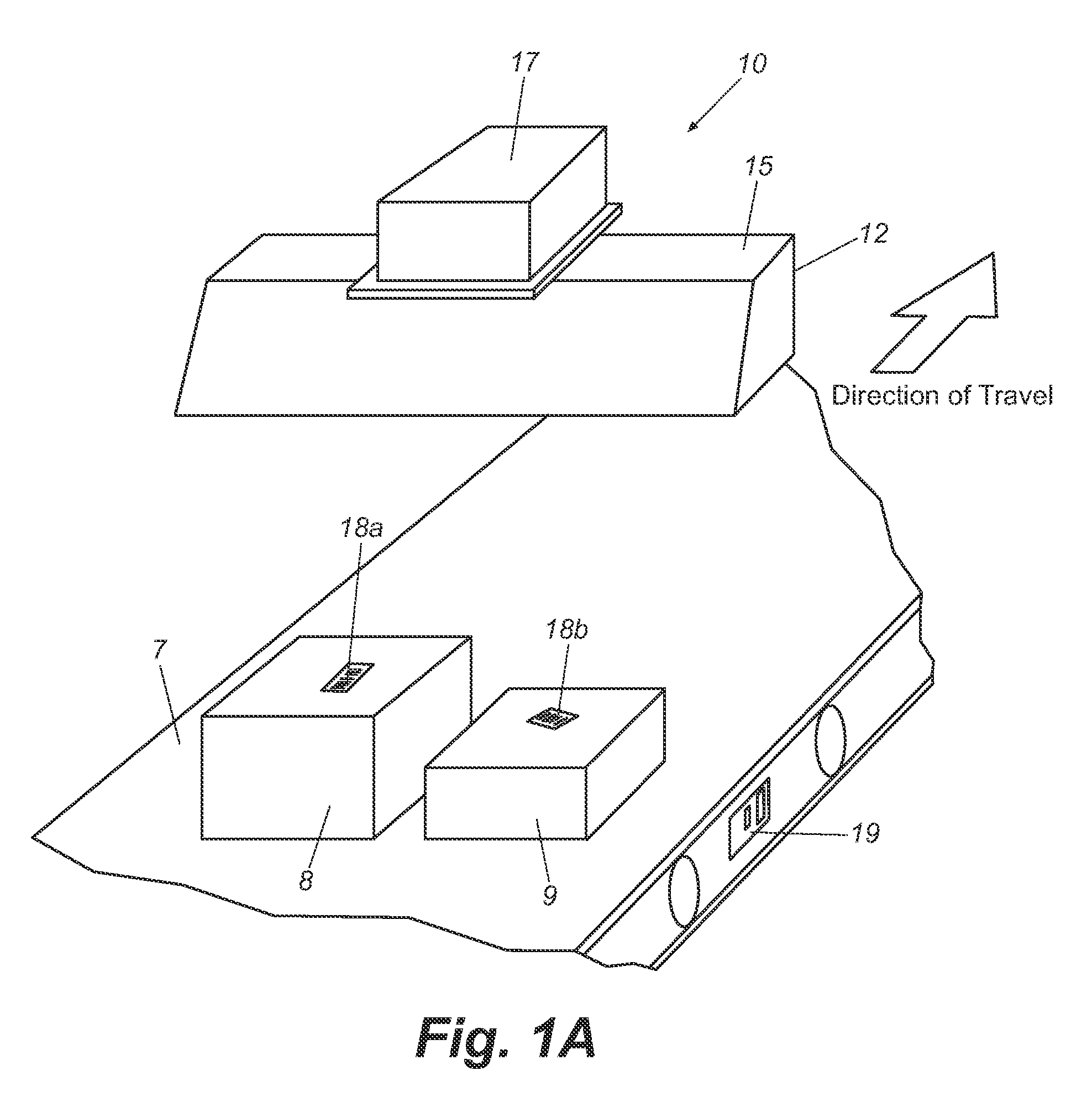
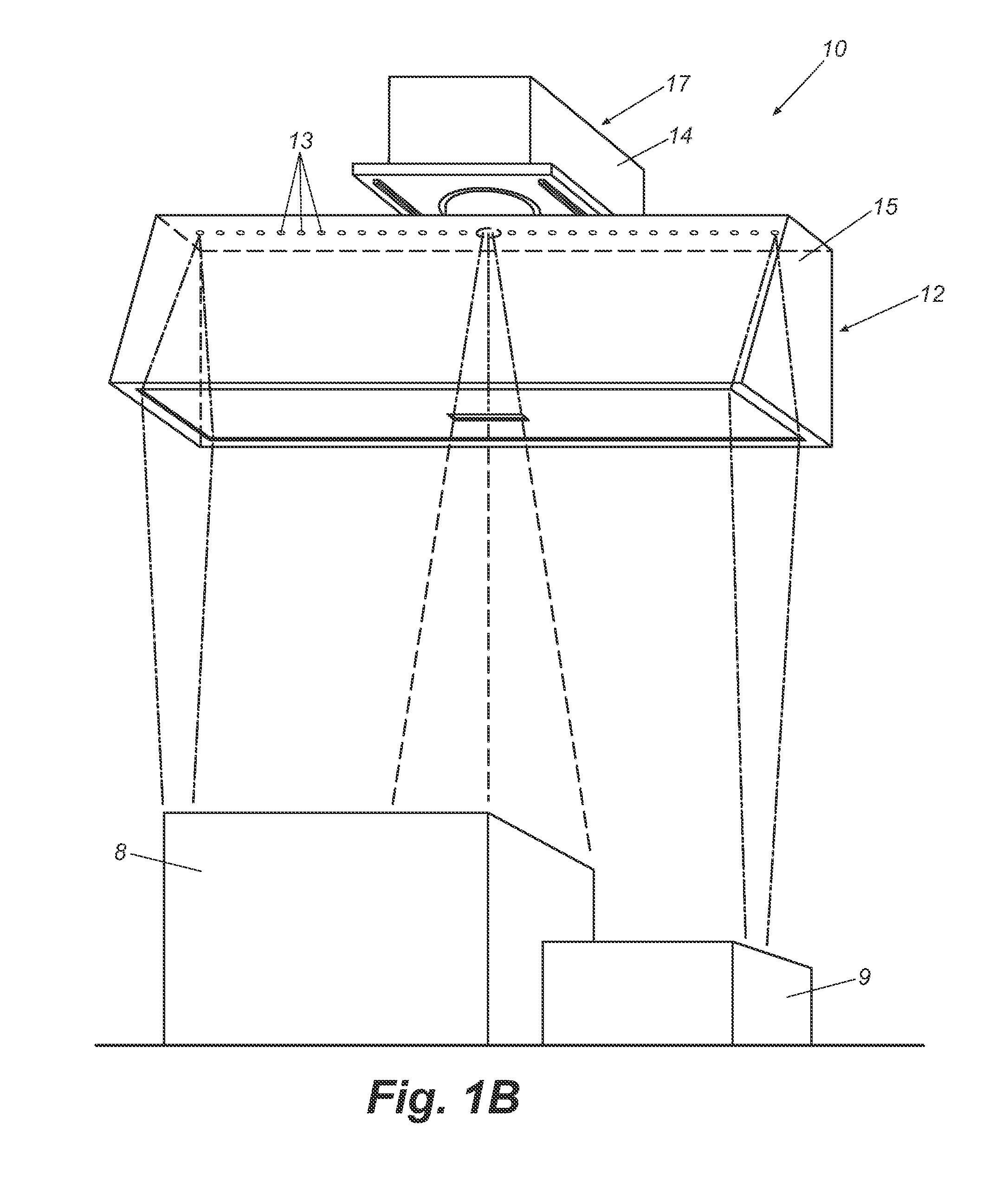
[0029] Reference will now be made in detail to presently preferred embodiments of the invention, one or more examples of which are illustrated in the accompanying drawings. Each example is provided by way of explanation of the invention, not limitation of the invention, In fact, it will be apparent to those skilled in the art that modifications and variations can be made in the present invention without departing from the scope or spirit thereof. For instance, features illustrated or described as part of one embodiment may be used on another embodiment to yield a still further embodiment. Thus, it is intended that the present invention covers such modifications and variations as come within the scope of the appended claims and their equivalents. Additional aspects and advantages of the invention will be set forth in part in the description which follows and, in part, will be obvious from the description, or may be learned by practice of the invention.

[0030] Certain terminology is ...


PUM


Abstract

A system for imaging an object comprising a surface for receiving the object to be imaged and an imaging device. The imaging device comprises a housing and a fixed focusing optical device mounted to the housing, whereby the fixed focusing optics comprises a lens for focusing light reflected from the object. A plurality of independent linear imaging sensors are positioned in the housing at different distances from the fixed focusing lens so that a face of each of the plurality of independent linear imaging sensors is aligned parallel to the surface. A processor is coupled to the plurality of independent linear imaging sensors for receiving an output signal from each of the plurality of independent linear imaging sensors representative of the reflected light. The lens defines a plane parallel to the surface, and the plurality of independent linear imaging sensors are adapted to receive reflected light from the object.

Description

CLAIM OF PRIORITY [0001] This application claims priority to U.S. Provisional Patent Application No. 60 / 737,118, filed Nov. 16, 2005, the entire disclosure of which is incorporated by reference herein.BACKGROUND [0002] The present invention relates generally to optical scanning systems, More particularly, this invention relates to a scanning system having a large depth of field which is capable of focusing on and scanning a plurality of targets over a wide range of distances. [0003] Various optical scanning systems have been developed for reading and decoding coded symbologies. Such optical scanning systems typically incorporate a light source and a light detecting means, such as a CMOS- or CCD-based image sensor. A portion of the light which is reflected from the coded symbology is detected by the image sensor and converted into an electrical signal, which is the basis for the digital image of the coded symbology that has been scanned. The digital image is then processed and decode...

Claims


Application Information

Patent Timeline
Patent Type & Authority Applications(United States)
IPC IPC(8): H01J40/14
CPCH04N1/04H04N1/195H04N1/12
Inventor WURZ, DAVID A.BROBST, THOMAS J.FREYMAN, CHRISTOPHER ALAN
Owner ACCU SORT SYST
Why Eureka
Try Eureka