Positioning ring structure for motor

a technology of positioning ring and motor, which is applied in the direction of machines/engines, positive displacement liquid engines, pumping machines, etc., can solve the problems of lowering the noise generated during the operation of the motor, preventing outflow and loss of lubricating oil, and prolonging the life of the motor.

Inactive Publication Date: 2007-07-19
SUNONWEALTH ELECTRIC MACHINE IND
View PDF5 Cites 5 Cited by
  • Summary
  • Abstract
  • Description
  • Claims
  • Application Information

AI Technical Summary

Benefits of technology

[0011] By such an arrangement, the lubricating oil that has flowed outward via the central hole of the positioning ring flows back into the axial tube via the at least one circulating hole under the action of pumping effect inside the axial tube. Thus, the at least one circulating hole provides at least one circulating path for the lubricating oil, prevents outflow and loss of the lubricating oil, protects the motor by preventing wear to the shaft and the bearing, and prolongs the life of the motor. Also, the noise generated during operation of the motor is lowered.

Problems solved by technology

Also, the noise generated during operation of the motor is lowered.

Method used


Image

  • Positioning ring structure for motor
  • Positioning ring structure for motor
  • Positioning ring structure for motor

Examples


first embodiment

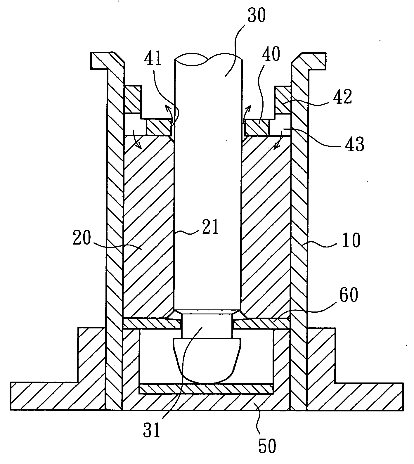
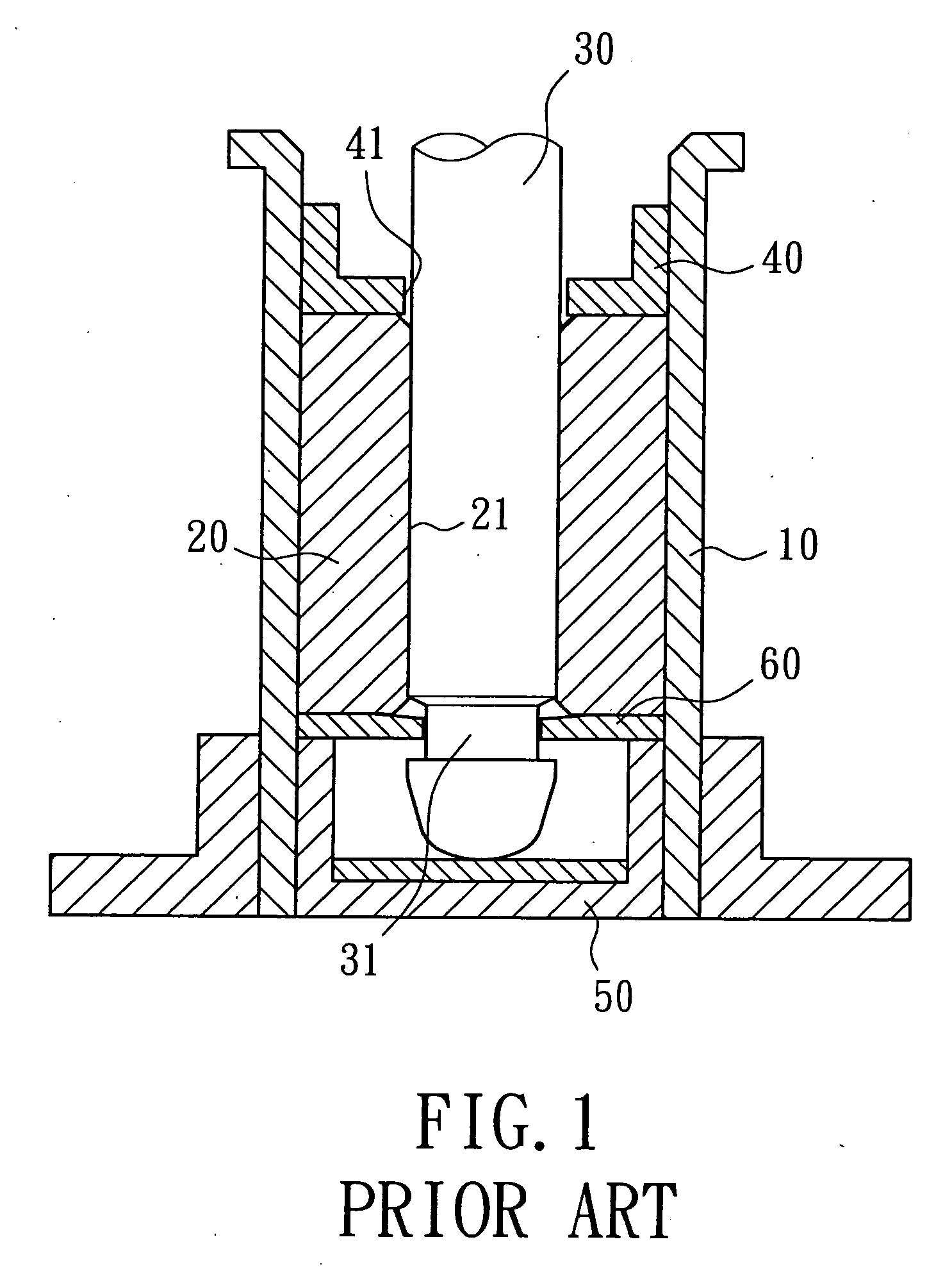
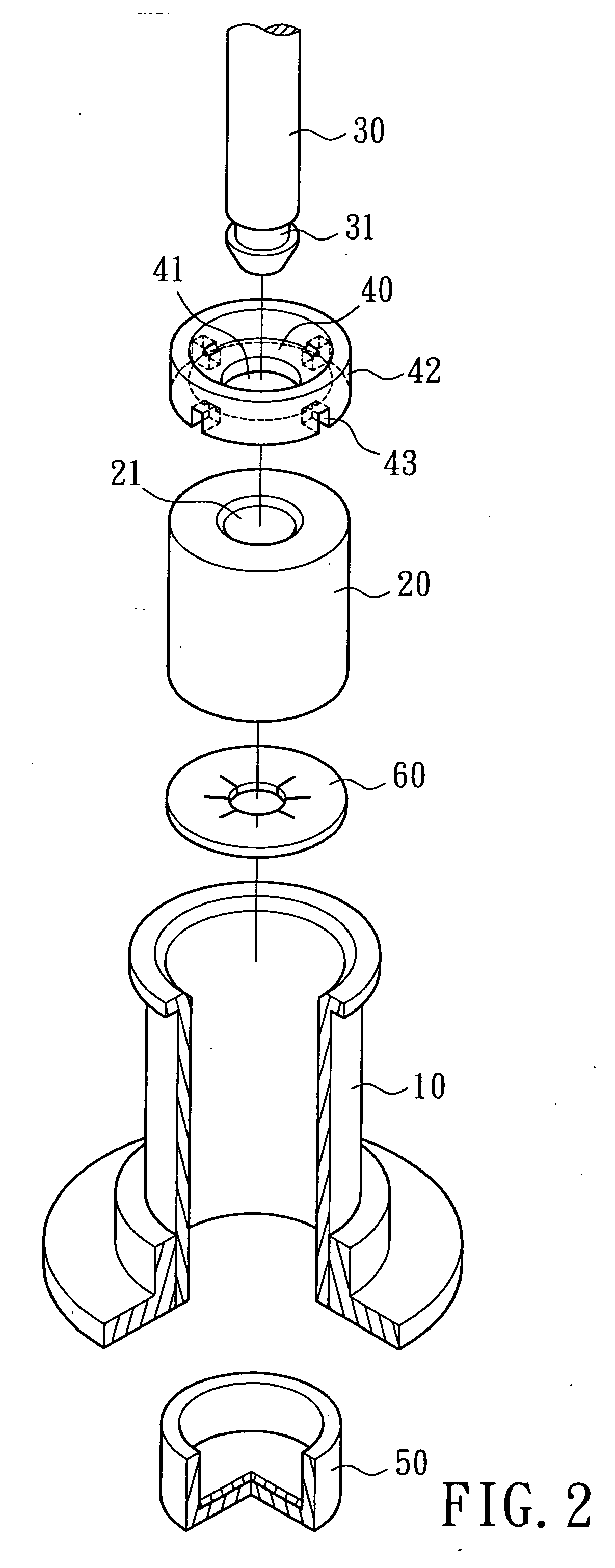
[0018]FIGS. 2 and 3 illustrate a first embodiment a positioning ring structure for a motor in accordance with the present invention. The positioning ring structure comprises an axial tube 10 in which an end cap 50, a retaining plate 60, a bearing 20, and a positioning ring 40 are mounted. The end cap 50 and the positioning ring 40 are in tight fit with an inner circumferential wall of the axial tube 10 and respectively located in two ends of the axial tube 10. Hence, the retaining plate 60 and the bearing 20 are arranged in desired positions in the axial tube 10.

[0019] A shaft 30 includes an annular groove 31 in an end thereof. The shaft 30 is extended through a central hole 41 of the positioning ring 40 and an axial hole 21 of the bearing 20 in sequence. The retaining plate 60 is engaged in the annular groove 31 of the shaft 30, preventing disengagement of the shaft 30 while the shaft 30 is rotating in the axial hole 21 of the bearing 20.

[0020] In this embodiment, the positioning ...

second embodiment

[0022]FIGS. 4 and 5 illustrate the present invention. In this embodiment, the positioning ring 40 is substantially a ring with a central hole 41. At least one circulating hole (four in this embodiment) 44 is defined in an outer circumference of the positioning ring 40 and faces the inner circumferential wall of the axial tube 10. The circulating holes 44 connect between an end face of the positioning ring 40 and the other end face of the positioning ring 40.

[0023] By such an arrangement, the lubricating oil that has flowed outward via the central hole 41 of the positioning ring 40 flows back into the axial tube 10 via the circulating holes 44 under the action of pumping effect inside the axial tube 10. Thus, the circulating holes 44 provide circulating paths for the lubricating oil, prevent outflow and loss of the lubricating oil, protect the motor by preventing wear to the shaft 30 and the bearing 20, and prolong the life of the motor. Also, the noise generated during operation of ...


PUM


Abstract

A positioning ring structure for a motor includes an axial tube, a bearing mounted in the axial tube, and a positioning ring mounted in the axial tube for retaining the bearing in place. The positioning ring includes a central hole extended through by a shaft. The positioning ring includes at least one circulating hole facing an inner circumferential wall of the axial tube. The circulating hole is a through-hole. The lubricating oil that has flowed outward via the central hole of the positioning ring flows back into the axial tube via the circulating hole. Thus, the circulating hole provides a circulating path for the lubricating oil, prevents outflow and loss of the lubricating oil, protects the motor by preventing wear to the shaft and the bearing, and prolongs the life of the motor.

Description

BACKGROUND OF THE INVENTION [0001] 1. Field of the Invention [0002] The present invention relates to a positioning ring structure for a motor. More particularly, the present invention relates to a positioning ring structure for a motor that allows circulation of lubricating oil, thereby preventing outflow and loss of the lubricating oil, protecting the motor by preventing wear to the shaft and the bearing, and prolonging the life of the motor. [0003] 2. Description of Related Art [0004] Lubricating oil provides lubrication for a shaft that rotates relative to a bearing for the purposes of reducing frictional force between the shaft and the bearing. Better circulation of the lubricating oil and loss-prevention of the lubricating oil are the keys to the reduced operational noise of the motor and to the prolonged life of the motor. [0005]FIG. 1 illustrates a motor with a conventional positioning ring structure. A bearing 20 is fixed in an axial tube 10 and sandwiched between a position...

Claims


Application Information

Patent Timeline
Patent Type & Authority Applications(United States)
IPC IPC(8): H02K5/16F04B17/00F16C19/50
CPCF16C17/02
Inventor HORNG, ALEXHUANG, SHIH-CHANG
Owner SUNONWEALTH ELECTRIC MACHINE IND
Why Eureka
Try Eureka