

Electronic device
a technology of electronic devices and display parts, applied in the field of electronic devices, can solve the problems of poor usability of devices, inability to provide a large screen, and inability to provide sufficient portability,
- Summary
- Abstract
- Description
- Claims
- Application Information
AI Technical Summary
Benefits of technology
Problems solved by technology
Method used
Image

Examples
first embodiment
1. First Embodiment
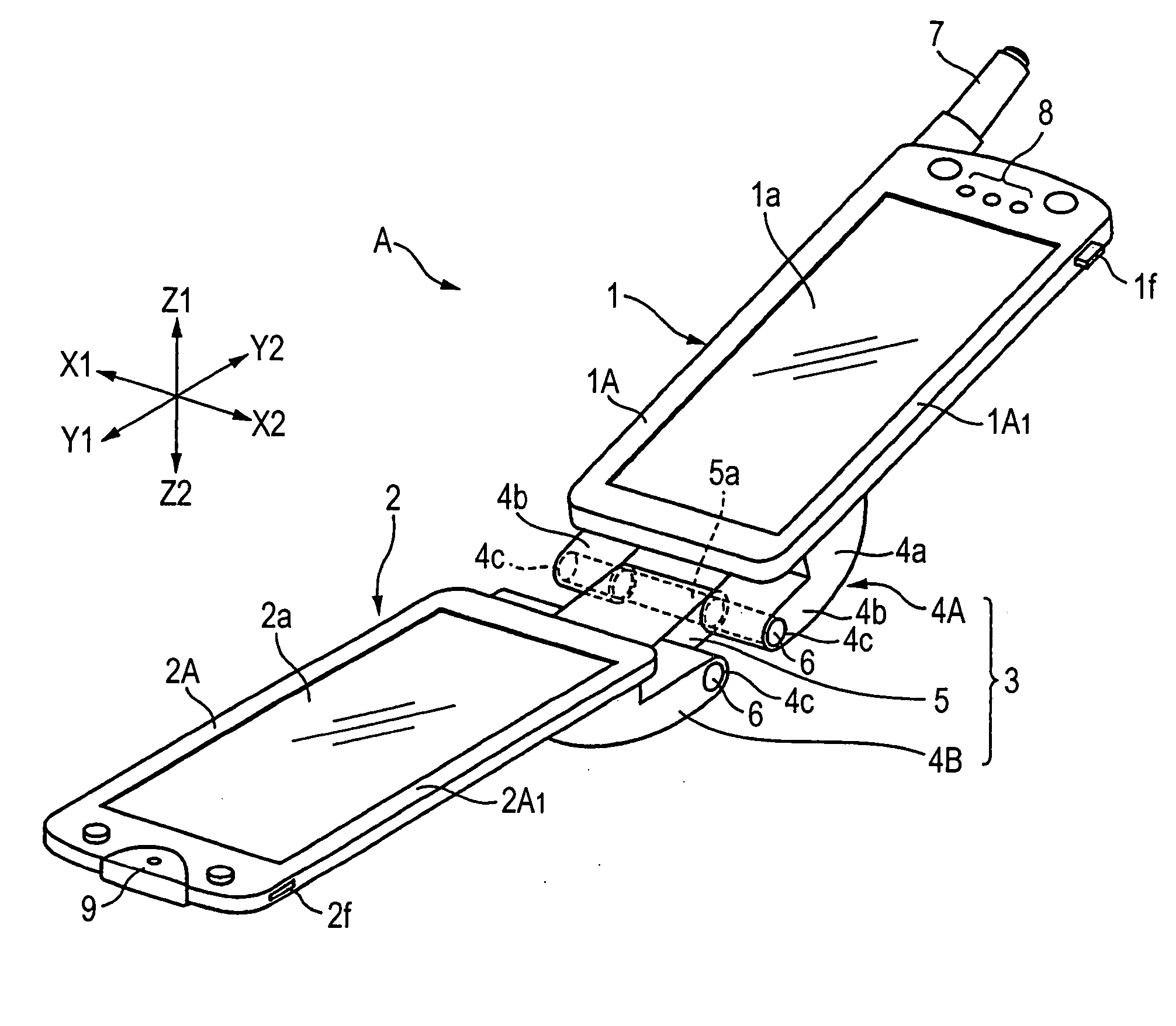
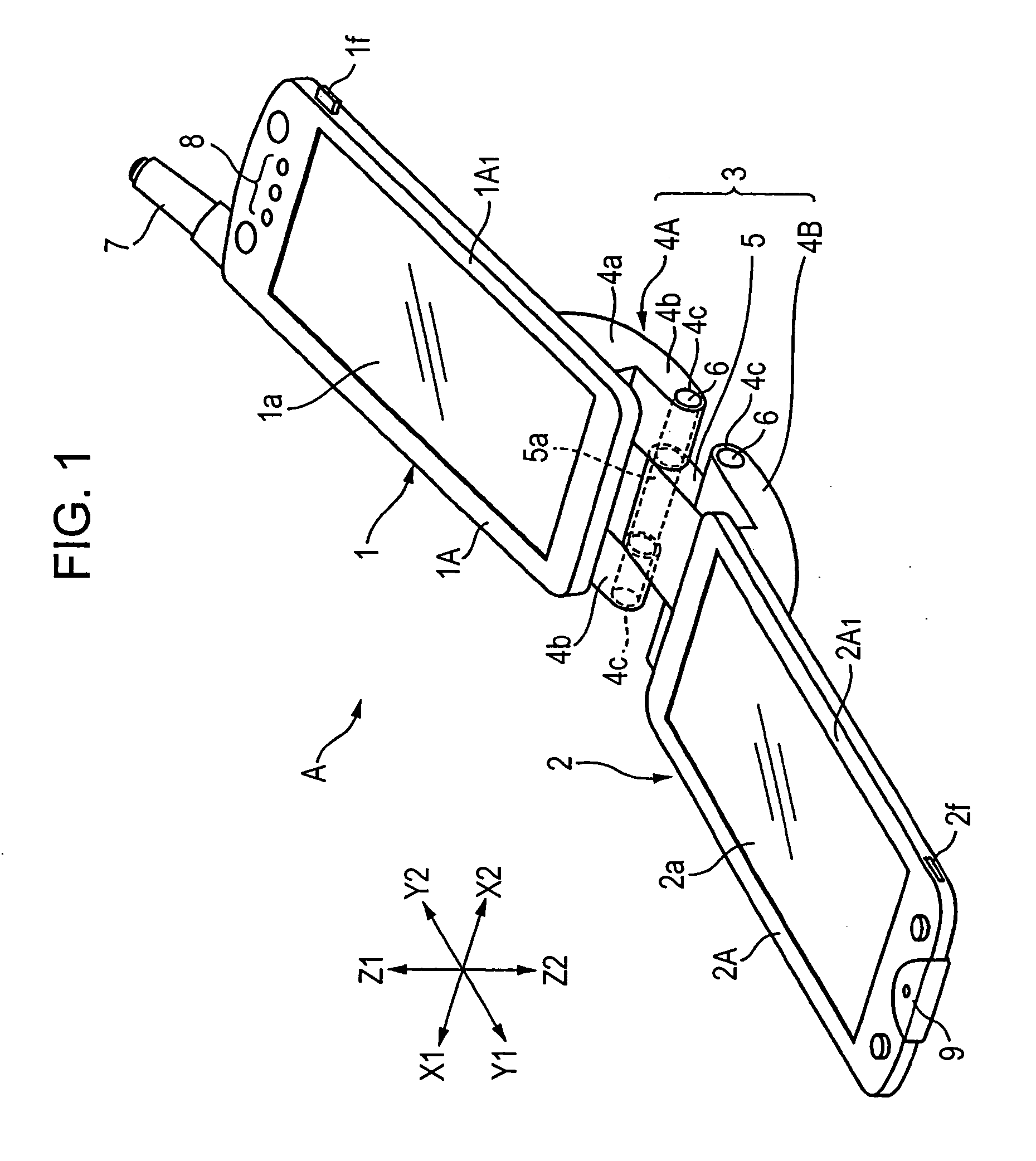
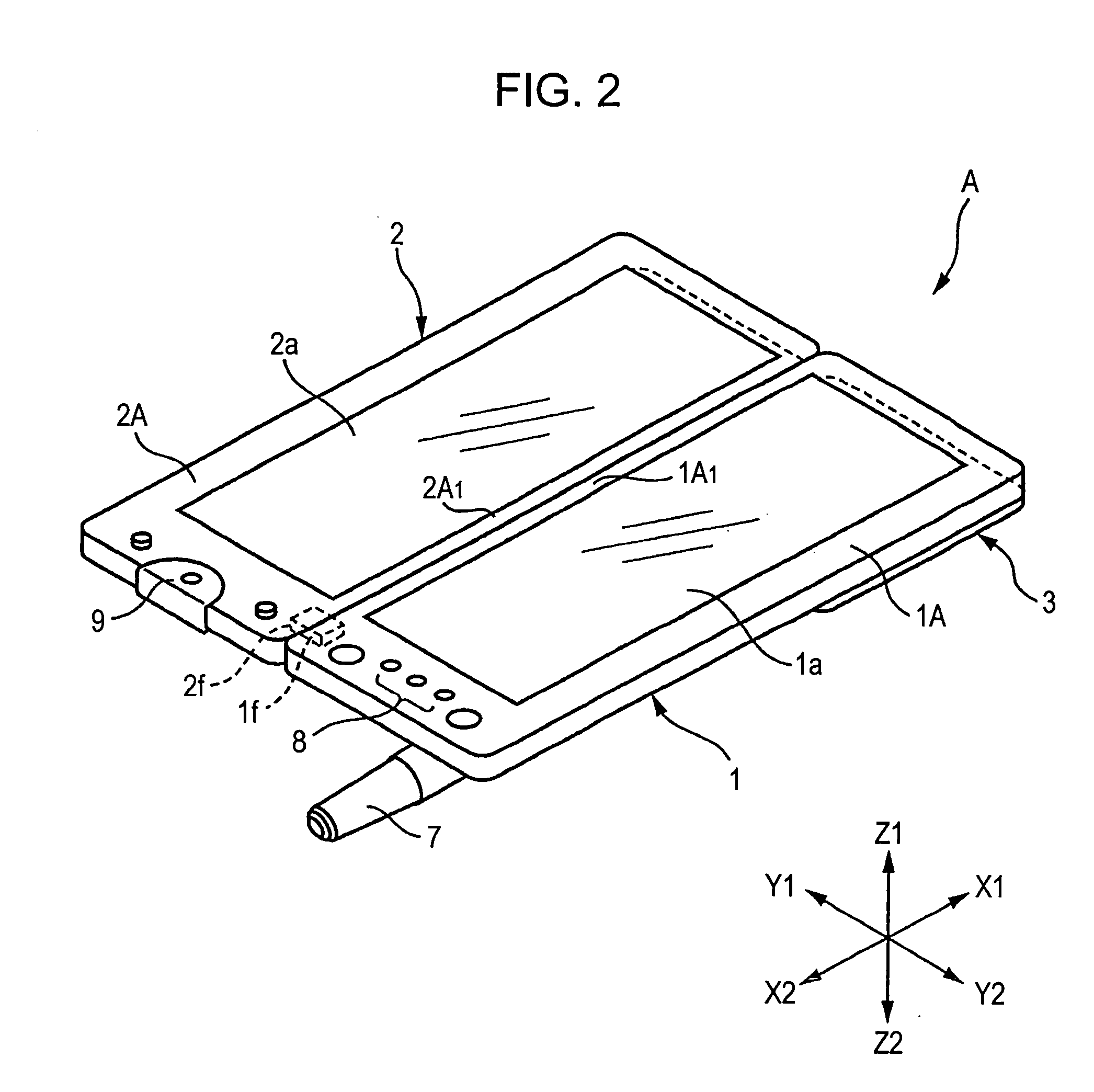
[0078]FIG. 1 is a perspective view of an electronic device according to a first embodiment of the present invention, showing a second mode in which display units of the electronic device are opened longitudinally. FIG. 2 is a perspective view of the electronic device in FIG. 1, showing a third mode in which the display units are opened laterally. FIG. 3 is a partial enlarged view showing coupled portions of coupling means and the display units. FIGS. 4 to 6 illustrate how the electronic device is operated. FIG. 4 is a side view showing a first mode in which the electronic device is closed. FIG. 5A is a side view showing the second mode as in FIG. 1. FIG. 5B is a back view showing the second mode as in FIG. 1. FIG. 6A is a side view showing the display units opened laterally after they are rotated. FIG. 6B is a back view of the electronic device shown in FIG. 6A.
[0079] Referring to FIG. 1, an electronic device A according to the first embodiment mainly includes a ...
second embodiment
2. Second Embodiment
[0111]FIGS. 8A to 8C illustrate an electronic device according to a second embodiment of the present invention. FIG. 8A is a plan view showing a first mode in which display units are folded so as to face each other. FIG. 8B is a plan view showing a third mode (large-screen state) in which first and first display units are adjacent to each other laterally. FIG. 8C is a plan view showing a second mode (open state) in which the display units are opened such that the first and second display portions are arranged longitudinally. FIGS. 8A and 8B show the backside of the electronic device while FIG. 8C shows the display side of the electronic device.
[0112] An electronic device B shown in FIG. 8 mainly includes a first display unit 11, a second display unit 12, and coupling means 13. The first and second display units 11 and 12 have substantially the same internal structure as those in the first embodiment; therefore, differences from the first embodiment are mainly de...
third embodiment
3. Third Embodiment
[0129] A portable information terminal according to a preferred embodiment of the present invention will now be described with reference to the drawings.
[0130] FIGS. 9 to 14 illustrate the embodiment of the present invention. FIG. 9 is a front view showing a form used as a cellular phone. FIG. 10 is an enlarged sectional view taken along line A-A in FIG. 1. FIG. 11 is an enlarged sectional view showing the engagement of a first protective plate used in this embodiment. FIG. 12 is a back view showing the form used as a cellular phone. FIG. 13 is a front view showing a form used for television or the Internet. FIG. 14 is a block diagram showing the main part of a signal-processing system used in this embodiment.
Basic Structure in the Embodiment
[0131] Referring to FIG. 9, the portable information terminal according to this embodiment has a first casing 101 including a first display portion 3 and a second casing 102 including a second display portion 110. The displ...
PUM
 Abstract
Description
Claims
Application Information