Vehicle Surrounding Image Display Device

a technology for displaying devices and vehicles, applied in television systems, instruments, transportation and packaging, etc., can solve problems such as significant distortion of the image of another vehicle located directly behind the user's own vehicle, and the center of the rear side of the vehicl

Active Publication Date: 2007-07-19
ALPINE ELECTRONICS INC
View PDF4 Cites 66 Cited by
  • Summary
  • Abstract
  • Description
  • Claims
  • Application Information

AI Technical Summary

Benefits of technology

[0013] According to the above vehicle surrounding image display device, the second image taken by the second camera which takes the image behind the vehicle from the position off the center in the width direction of the vehicle is deformed such that at least the portion of the inner side in the vehicle width direction of the second image lower than the vanishing point in the second image is inclined to make the lower portion of the inner side located more outward in the vehicle width direction than the upper portion of the inner side, and that the inclination is gradually increased toward the lower end of the inner side. The deformed image is then synthesized with the first image taken by the first camera which takes the image behind the vehicle from the central position in the width direction of the vehicle. Thereby, a single synthetic image simulating the circumstances behind the user's own vehicle as observed from a single virtual viewpoint is generated, and the generated image is displayed on the display device. With the second image taken by the second camera thus deformed and combined, distortion of the images of other vehicles and the like located directly behind the user's own vehicle and diagonally behind the user's own vehicle on the left and right sides can be suppressed to a small amount by reducing the degree of deformation of the images in a range including these other vehicles and the like, while suppressing the occurrence of the misalignment of the white lines on the road surface and the like at the boundaries between the respective images near the own vehicle, i.e., the prominently observable misalignment of the white lines on the road surface and the like. Accordingly, it is possible to display a synthetic image simulating the circumstances behind the user's own vehicle as observed from a single virtual viewpoint in a more realistic form.
[0018] As described above, according to the present invention, it is possible to generate an image simulating the circumstances behind a user's own vehicle as observed from a single virtual viewpoint in a form as realistic as possible on the basis of images behind the vehicle taken by a plurality of cameras, and to provide the generated image to a user of the vehicle.

Problems solved by technology

With this configuration, however, the image of another vehicle located directly behind the user's own vehicle (i.e., another vehicle whose image is taken by the camera provided at the center of the rear side of the vehicle) is significantly distorted.
In this case, however, while the significant distortion of the image of another vehicle located directly behind the user's own vehicle is suppressed, the images of other vehicles located diagonally behind the user's own vehicle on the left and right sides (i.e., other vehicles whose images are taken by the cameras provided with the rearview mirrors on the left and right sides of the vehicle) are significantly distorted.
Thus, the technique described in the publicly known document is unable to generate an image which simulates the circumstances behind a user's own vehicle as observed from a single virtual viewpoint in a sufficiently realistic form.

Method used


Image

  • Vehicle Surrounding Image Display Device
  • Vehicle Surrounding Image Display Device
  • Vehicle Surrounding Image Display Device

Examples


Embodiment Construction

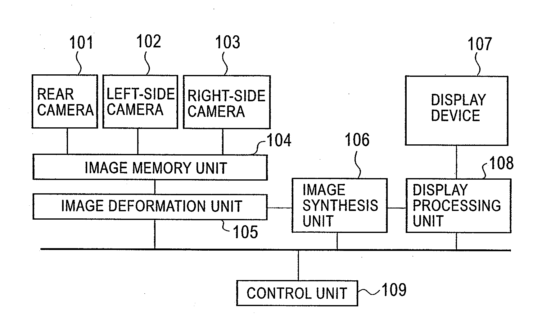
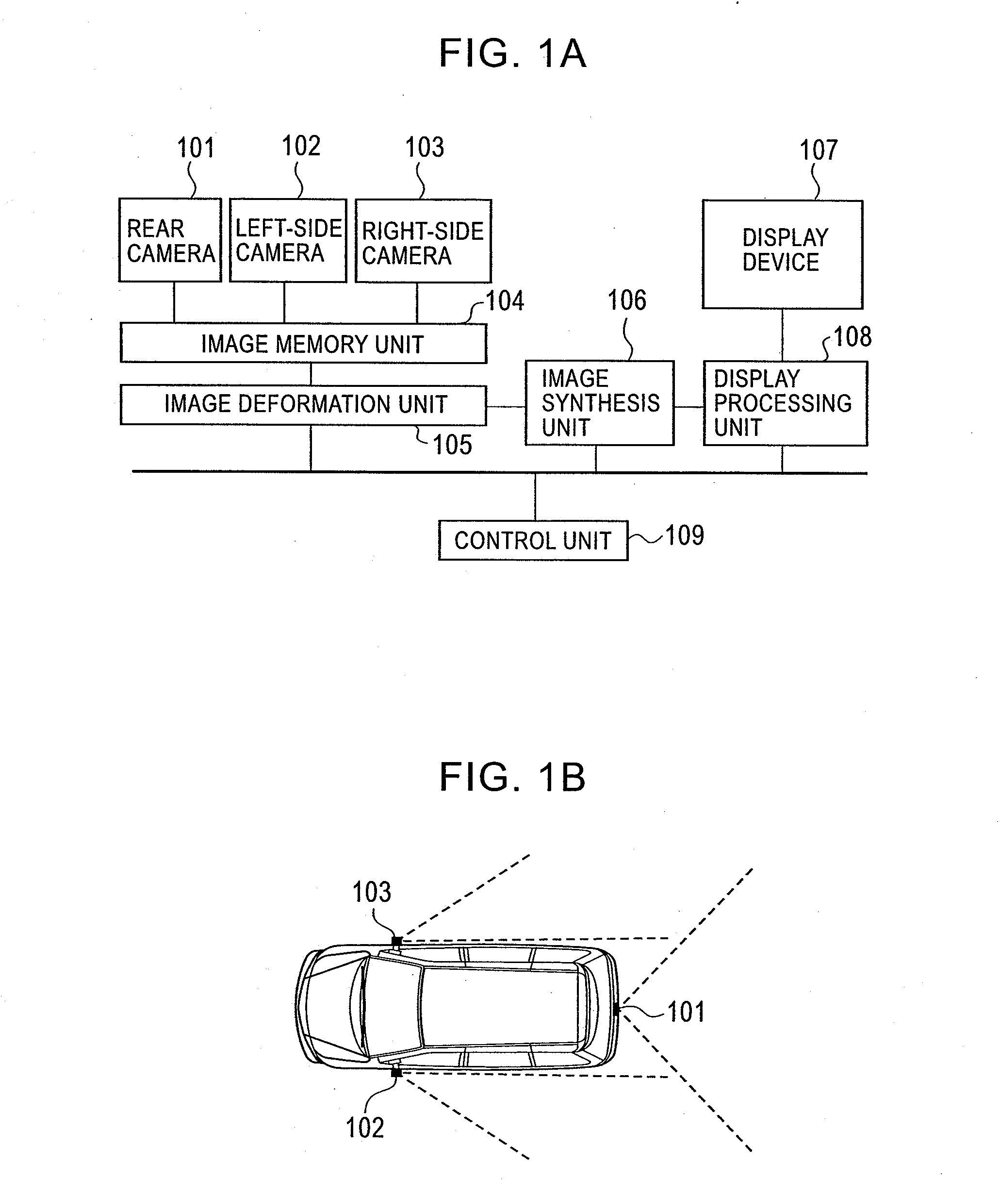
[0023] An embodiment of the present invention will now be described. As illustrated in FIGS. 1A and 1B, a vehicle surrounding image display device according to an embodiment of the present invention includes a rear camera 101 provided at the center of the rear side of a vehicle for taking an image behind the vehicle, a left-side camera 102 provided with a rearview mirror on the left side of the vehicle for taking an image behind the vehicle on the left side, a right-side camera 103 provided with a rearview mirror on the right side of the vehicle for taking an image behind the vehicle on the right side, an image memory unit 104 for retaining the images taken by the respective cameras, an image deformation unit 105, an image synthesis unit 106, a display device 107 provided in the interior of the vehicle, a display processing unit 108 for controlling the display on the display device 107, and a control unit 109 for controlling the above respective components.

[0024] In the above confi...


PUM


Abstract

A vehicle surrounding image display device according to the present invention combines an image obtained by reducing in size an image taken by a camera provided at the center of the rear side of a vehicle, and images obtained by deforming images taken by cameras provided at the left and right sides of the vehicle such that the outward inclination of the inner side in the vehicle width direction of each of the left and right side images is gradually increased toward the lower end of the inner side. The vehicle surrounding image display device then generates a single image simulating the circumstances behind the user's own vehicle as observed from a single virtual viewpoint in a realistic form, and displays the generated image on a display device.

Description

BACKGROUND OF THE INVENTION [0001] 1. Related Applications [0002] The present application claims priority to Japanese Patent Application Number 2005-346699, filed Nov. 30, 2005, the entirety of which is hereby incorporated by reference. [0003] 2. Field of the Invention [0004] The present invention relates to a technique of providing a driver of a vehicle with an image showing the surroundings of the vehicle. [0005] 3. Description of the Related Art [0006] As a technique of providing a driver of a vehicle with an image of the surroundings of the vehicle, Japanese Unexamined Patent Application Publication No. 10-257482 (hereinafter referred to as the publicly known document), for example, describes a technique of generating and displaying a composite image synthesized from images behind the vehicle taken by three cameras provided at three locations, i.e., rearview mirrors on the left and right sides of the vehicle and the center of the rear side of the vehicle. [0007] a to e in FIG. 5...

Claims


Application Information

Patent Timeline
Patent Type & Authority Applications(United States)
IPC IPC(8): H04N7/18
CPCB60R1/00B60R2300/804B60R2300/303B60R2300/105
Inventor YUASA, MIZUKIKUBOTANI, SHIGEJI
Owner ALPINE ELECTRONICS INC
Why Eureka
Try Eureka