Ultrasonic diagnosis apparatus

a diagnostic device and ultrasonic technology, applied in the field of ultrasonic diagnostic devices, can solve the problems of reducing the realtime characteristic, not being able to achieve accurate diagnosis, and not being able to achieve realistic resolution

Inactive Publication Date: 2007-07-19
OLYMPUS MEDICAL SYST CORP
View PDF13 Cites 95 Cited by
  • Summary
  • Abstract
  • Description
  • Claims
  • Application Information

AI Technical Summary

Benefits of technology

[0014] Accordingly, it is an object of the present invention to provide an ultrasonic diagnosis apparatus which allows the secure display of the path of insertion of a puncture needle.

Problems solved by technology

Then, whether the end of the puncture needle has reached to the inside of a tumor or not cannot be checked, and the accurate diagnosis may not be performed as it is.
Japanese Unexamined Patent Application Publication No. 2000-185041 may require the sacrifice of the frame rate for performing three-dimensional scanning in Doppler mode, which may decrease the realtime characteristic during a centesis operation and may not be a realistic resolution.
Furthermore, in the technology disclosed in the publication, slight vibrations must be continuously applied to the puncture needle, which complicates the construction of the apparatus.
According to Japanese Unexamined Patent Application Publication No. 2004-208859, the ultrasonic data includes many pixels having closer luminance values, which makes the accurate extraction of the puncture needle only difficult in reality.
The technology disclosed in the publication has a problem that the actual path of insertion of the puncture needle cannot be checked since the puncture needle itself is not displayed though the amount of displacement of the puncture needle from the scanned surface is displayed.
Therefore, it is significantly difficult to correct the position of the ultrasonic transducers and / or the orientation of the tip of the puncture needle.

Method used


Image

  • Ultrasonic diagnosis apparatus
  • Ultrasonic diagnosis apparatus
  • Ultrasonic diagnosis apparatus

Examples


first embodiment

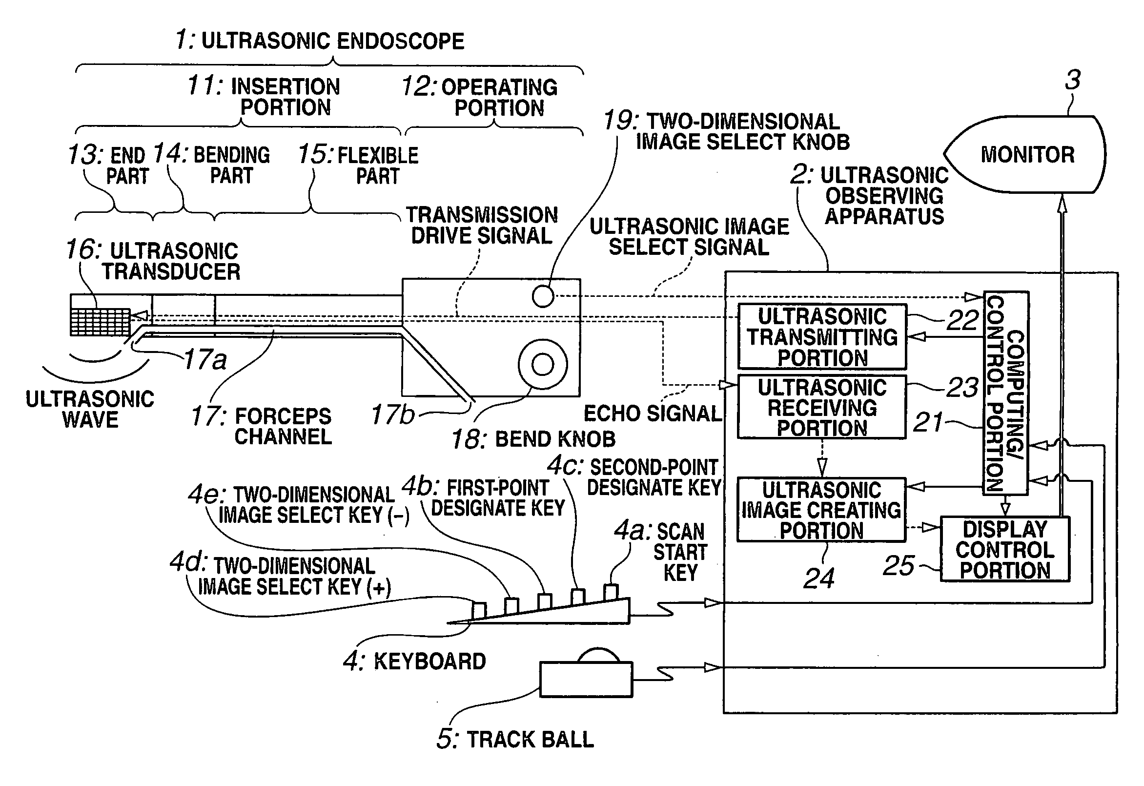
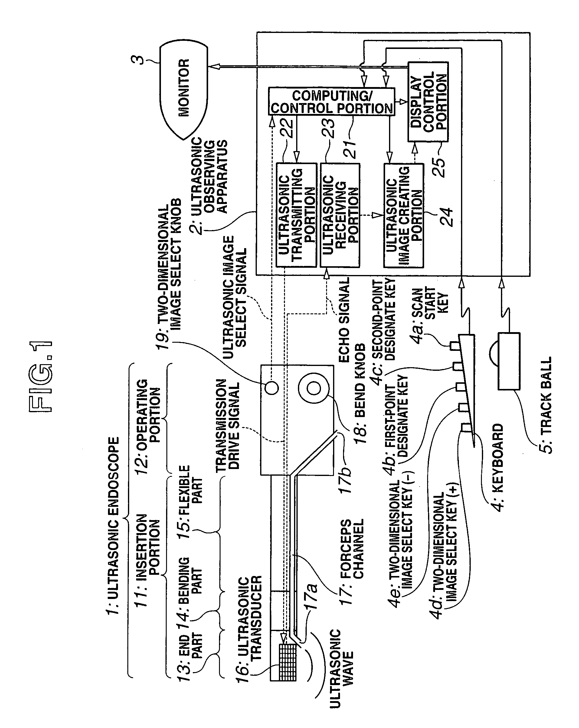
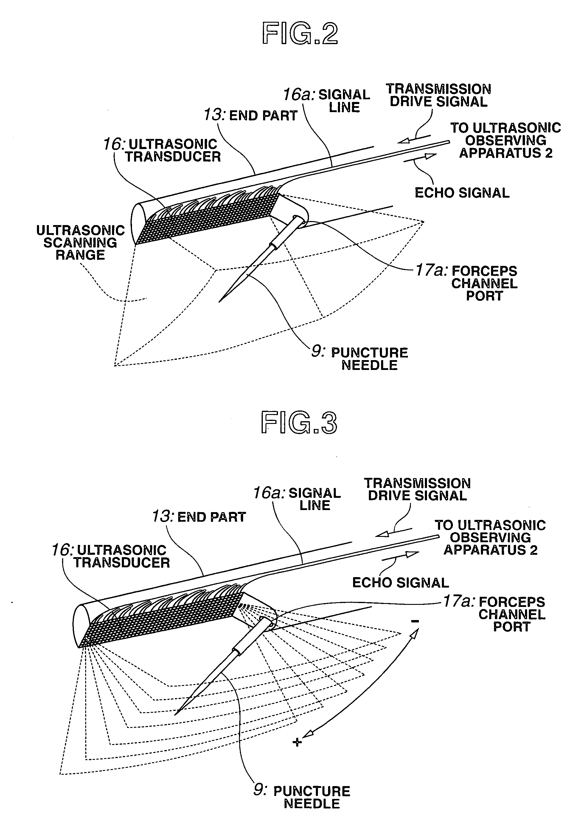
[0027] FIGS. 1 to 7 show a first embodiment of the present invention, and FIG. 1 is a diagram showing a configuration of an ultrasonic diagnosis apparatus; FIG. 2 is an enlarged perspective diagram showing a configuration of the end part of the ultrasonic endoscope; FIG. 3 is a diagram showing the comparison between the position of a two-dimensional ultrasonic image extracted in accordance with an operation on a two-dimensional image select key and the end part of the ultrasonic endoscope; FIG. 4 is a diagram showing an example in which the longitudinal axis of a puncture needle is rendered within a two-dimensional ultrasonic image on a monitor screen; FIG. 5 is a diagram showing a state that the first point is designated by moving the cursor to the basal position of the puncture needle on a two-dimensional ultrasonic image on the monitor screen; FIG. 6 is a diagram showing a state that the second point is designated by moving the cursor to the tip position of the puncture needle on...

second embodiment

[0097]FIGS. 8 and 9 show a second embodiment of the preset invention. FIG. 8 is a diagram showing a configuration of an ultrasonic diagnosis apparatus, and FIG. 9 is an enlarged diagram showing the tip of a stylet having a puncture needle and a first transmitting coil.

[0098] According to the second embodiment, the same reference numerals are given to the same components as those of the first embodiment, and the repetitive description thereof will be omitted herein. Mainly, differences will be only described.

[0099] According to this embodiment, the ultrasonic diagnosis apparatus of the second embodiment is different from that of the first embodiment shown in FIG. 1 in following points.

[0100] First of all, referring to FIG. 9, the tips of the puncture needle 9 and stylet 44 will be described.

[0101] The puncture needle 9 is a therapeutic device to be stuck into a living body and has a hollow structure allowing the suction of cells, for example, or injection of ethanol, for example....


PUM


Abstract

An ultrasonic diagnosis apparatus according to the present invention includes an ultrasonic endoscope having ultrasonic transducers for scanning ultrasonic wave in a living body three-dimensionally, an ultrasonic image creating portion of an ultrasonic observing apparatus for creating ultrasonic volume data based on an ultrasonic signal captured by the ultrasonic endoscope, a two-dimensional image select knob, keyboard, trackball, computing/control portion and display control portion for selecting a tomographic plane from the ultrasonic volume data by designating the angle of rotation about the straight line through two points designated on the ultrasonic volume data as the axis of rotation, and a monitor for displaying the tomographic plane selected during a scanning operation as a two-dimensional ultrasonic image.

Description

CROSS REFERENCES TO RELATED APPLICATIONS [0001] The present invention contains subject matter related to Japanese Patent Application No. 2005-380209 filed in the Japanese Patent Office on Dec. 28, 2005, the entire contents of which are incorporated herein by reference. BACKGROUND OF THE INVENTION [0002] 1. Field of the Invention [0003] The present invention relates to an ultrasonic diagnosis apparatus for creating an ultrasonic image from ultrasonic signals obtained by exchanging ultrasonic wave with the inside of a living body. [0004] 2. Description of the Related Art [0005] An ultrasonic diagnosis apparatus has been widely spread in recent years that transmits ultrasonic wave to the inside of a living body and receives the reflected waves from a biological tissue to observe the state of the living body as an image since the condition within the living body can be observed in realtime. [0006] When a tumor is found during the observation by using the ultrasonic diagnosis apparatus, ...

Claims


Application Information

Patent Timeline
Patent Type & Authority Applications(United States)
IPC IPC(8): A61B8/00
CPCA61B8/0833A61B8/0841A61B8/12A61B8/4488G01S15/8993A61B8/467A61B8/483A61B8/523G01S7/52074A61B8/463A61B8/466
Inventor IKUMA, SOICHIKAWASHIMA, TOMONAOKOMURO, MASAHIKOOTANI, SHUJIADACHI, HIDEO
Owner OLYMPUS MEDICAL SYST CORP
Why Eureka
Try Eureka