
Microstructured belt contact surface

a microstructured, contact surface technology, applied in the field of transport belts, can solve the problems of disturbance of liquid film otherwise generated between these surfaces, impairment of quality, etc., and achieve the effect of lessening the problem of intensive adhesion and not impairing the quality of finished web material

Inactive Publication Date: 2007-07-26
VOITH PATENT GMBH
View PDF7 Cites 1 Cited by
  • Summary
  • Abstract
  • Description
  • Claims
  • Application Information

AI Technical Summary

Benefits of technology

[0008]The invention provides a transport belt, in particular for machines for the production of web material such as paper or paperboard, with which it is possible to lessen the problem of intensive adhesion between the web material and the transport belt essentially without impairing the quality of the finished web material.
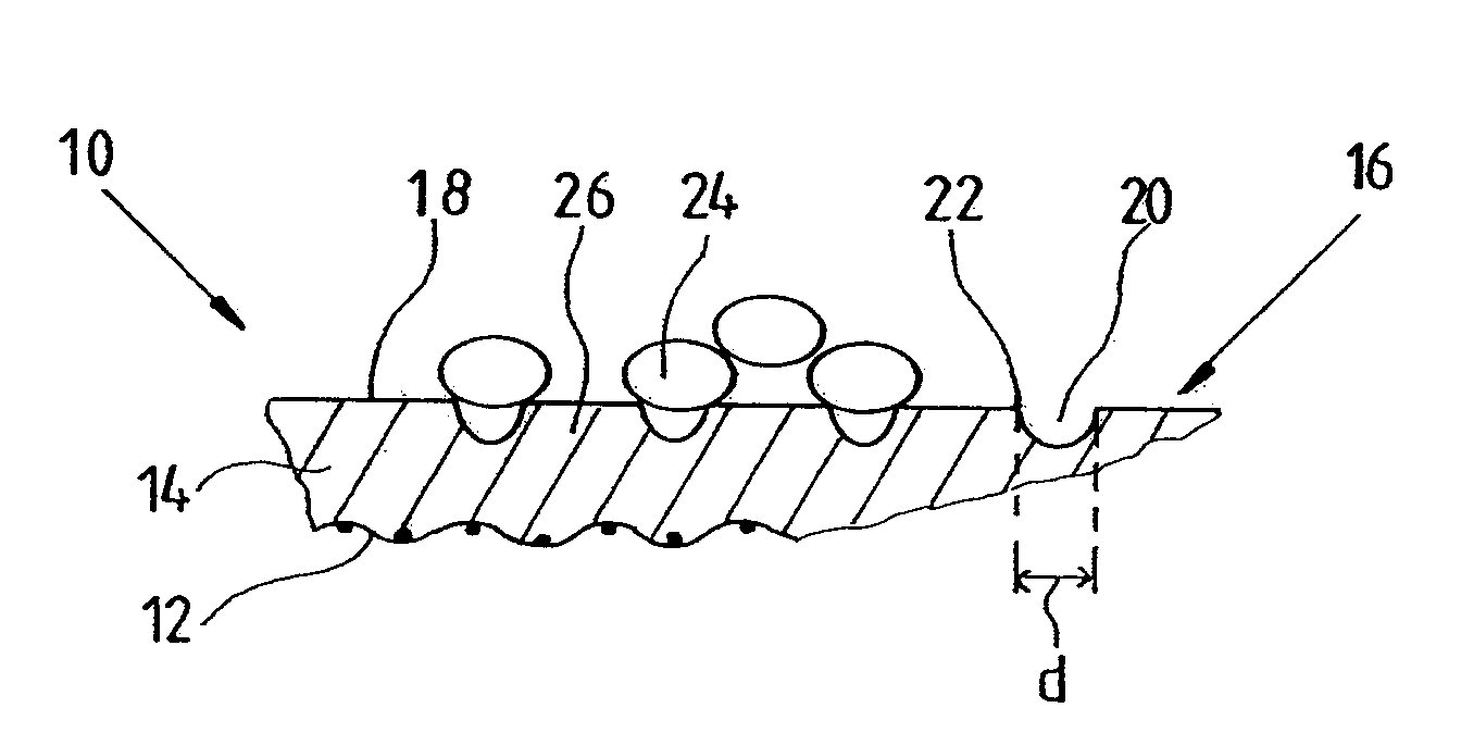
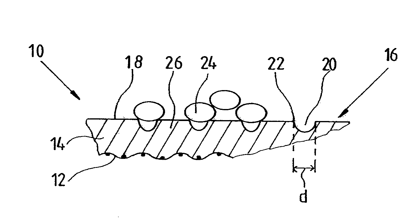
[0010]As a basis of the current invention it is assumed that, for the production of web material such as paper or paperboard, a starting material is used which is essentially comprised of very small fibers. By providing depressions which, at least in one direction, are not wider than 20 μm, it is assured that the fibers contained in the web material are unable to submerge in said depressions. However, because the fibers have a larger cross-sectional dimension than the previously mentioned dimension of the depression openings, the fibers run over the depressions existing on the web material contact side. Hence the depressions are still able to pick up liquid and ensure that no excessively strong adhesive effect is generated upon separation of the web material from the transport belt, while at the same time the risk of the web material surface being marked by structuring of the transport belt can be greatly lessened.

Problems solved by technology

By providing such depressions on the web material contact side of a transport belt an attempt is made to discharge at least a part of the liquid from the surface region between the transport belt and the web material, thus creating disturbances in a liquid film otherwise generated between these surfaces.
However, a problem caused by such a surface structuring, by the introduction of such depressions is that the direct contact between the web material and the contact belt generates an accordingly structured image in the surface of the web material.
In other words, the introduction of depressions produces a marking effect that may lead to impairments of quality.

Method used


Image

  • Microstructured belt contact surface
  • Microstructured belt contact surface

Examples


Embodiment Construction

[0017]The particulars shown herein are by way of example and for purposes of illustrative discussion of the embodiments of the present invention only and are presented in the cause of providing what is believed to be the most useful and readily understood description of the principles and conceptual aspects of the present invention. In this regard, no attempt is made to show structural details of the present invention in more detail than is necessary for the fundamental understanding of the present invention, the description taken with the drawings making apparent to those skilled in the art how the several forms of the present invention may be embodied in practice.

[0018]The FIGURE illustrates a transport belt 10 constructed according to the invention. The transport belt 10 has, in a central region, a reinforcement 12 which provides for the structural cohesion of the transport belt 10, and in particular the required tensile strength. The reinforcement 12 can comprise a fiber fabric ...


PUM

PropertyMeasurementUnit
diameteraaaaaaaaaa
diameteraaaaaaaaaa
diameteraaaaaaaaaa

Abstract

A transport belt, in particular for machines for the production of web material such as paper or paperboard, has, on a web material contact side, depressions of which the majority has a depression opening with a dimension smaller than 20 μm in at least one direction.

Description

CROSS-REFERENCE TO RELATED APPLICATIONS[0001]The present application claims priority under 35 U.S.C. § 119 of German Patent Application No. 10 2006 003 706.5 filed Jan. 26, 2006, the disclosure of which is expressly incorporated by reference herein in its entirety.BACKGROUND OF THE INVENTION[0002]1. Field of the Invention[0003]This invention relates to a transport belt that can be used on machines for the production of web material, for example paper or paperboard.[0004]2. Background Description[0005]From U.S. Pat. No. 6,331,231 B1 there is known a transport belt for paper machines which has, on a web material contact side provided to come into contact with a web material to be produced or processed, depressions in a surface otherwise constructed to be flat. These depressions are generated by inserting so-called microcapsules, which have a diameter in the range from 20 μm to 40 μm, into the construction material. After finishing of the transport belt the microcapsules positioned nea...

Claims


Application Information

Patent Timeline
Patent Type & Authority Applications(United States)
IPC IPC(8): D03D3/02D21F3/00
CPCD21F3/0227D21F7/086D21F7/083D21F3/0236
Inventor WESTERKAMP, ARVED H.WALKENHAUS, HUBERT
Owner VOITH PATENT GMBH
Learn More