Multi-axis bubble vial device

Active Publication Date: 2007-07-26
TRIMBLE NAVIGATION LTD
View PDF16 Cites 13 Cited by
  • Summary
  • Abstract
  • Description
  • Claims
  • Application Information

AI Technical Summary

Benefits of technology

[0013] The sides of the fluid chamber between the curved upper surface and the opposite surface are preferably light absorbing, whereby extraneous light reflections are reduced. The bubble vial may be shielded from extraneous l

Problems solved by technology

This, in turn, means that all associated components cannot be mounted on a single circuit board.
This level vial arrangement has the disadvantage of requiring components above and below the vial in order to determine the position of the beam.
The disadvantage of this arrangement is that

Method used


Image

  • Multi-axis bubble vial device
  • Multi-axis bubble vial device
  • Multi-axis bubble vial device

Examples


Example

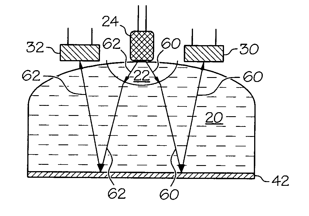
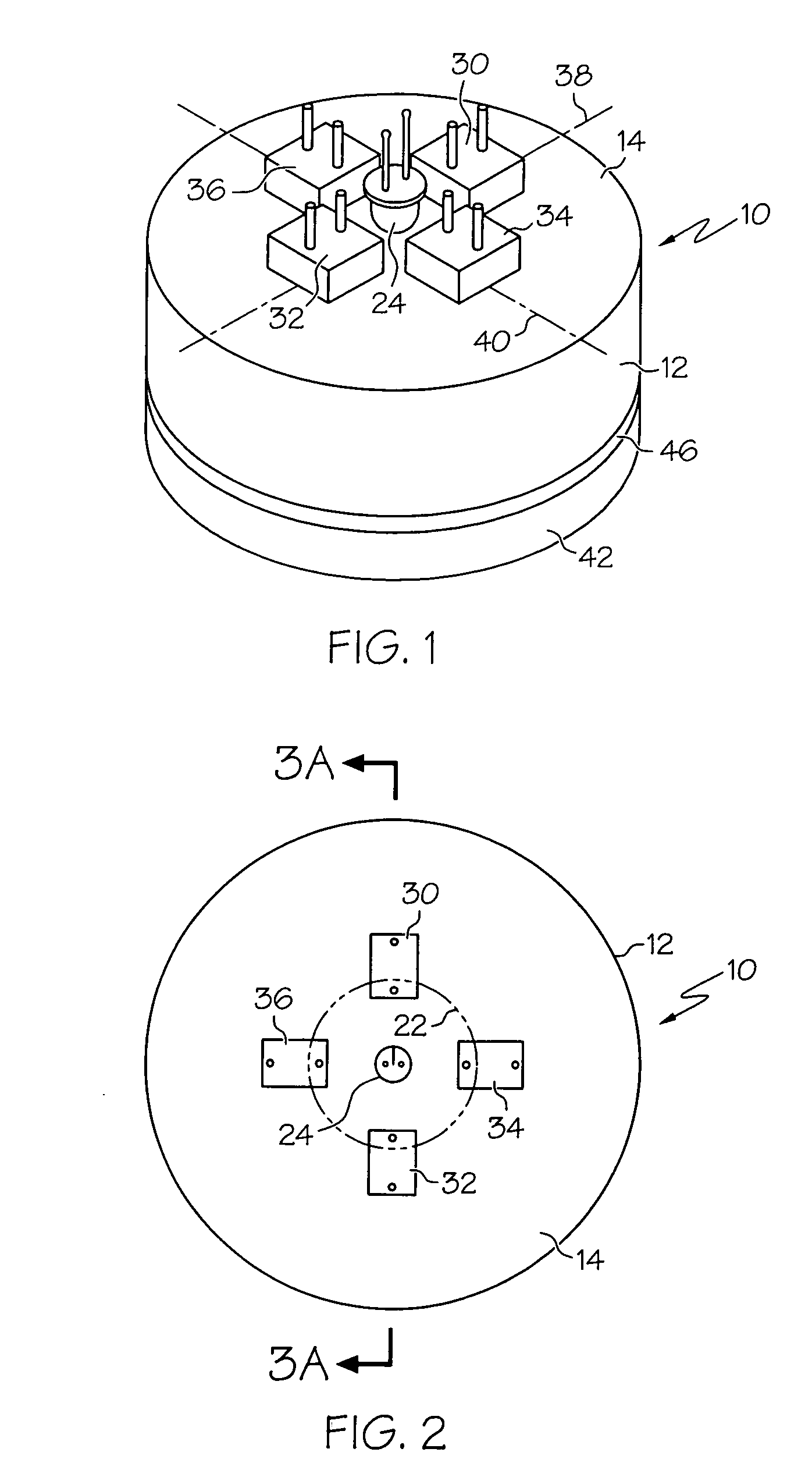
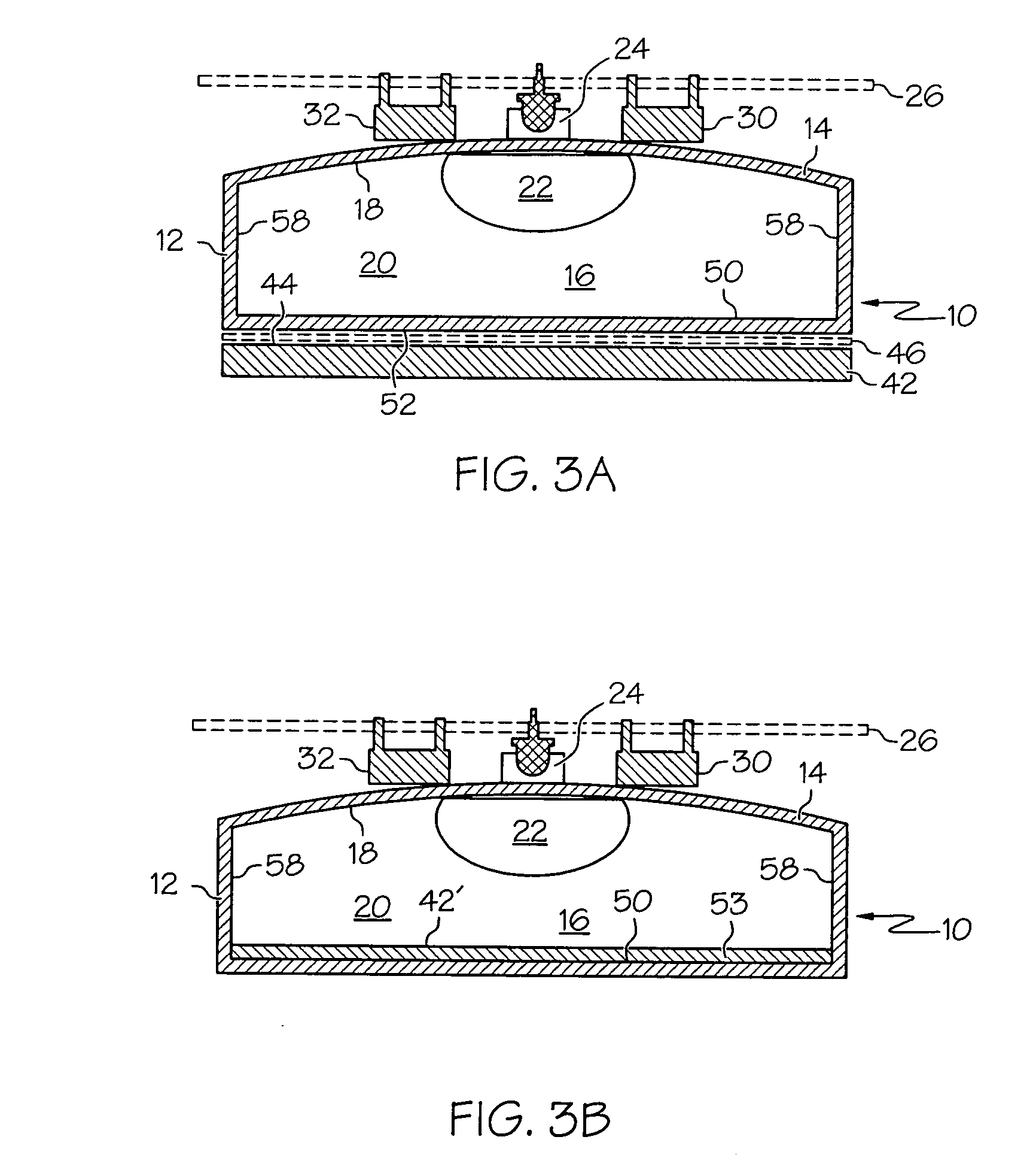
[0023] The present invention relates to a multi-axis bubble vial device, and to a multi-axis orientation determination device using such a bubble vial device. The bubble device 10 is shown in FIGS. 1, 2 and 3A. The device includes a bubble vial 12 having a vial body 14 that defines a fluid chamber 16 with a curved upper surface 18. As will become apparent, at least the upper portion of the bubble vial body 14 defining the curved surface 18 is transparent. A quantity of fluid 20 partially fills the chamber 16, trapping a gas bubble 22 in the upper portion of the chamber 16. The bubble 22 moves along the upper surface 18 in dependence upon the orientation of the vial. This is illustrated diagrammatically in FIGS. 5A and 5B, and will be discussed in greater detail, below.

[0024] The bubble vial device 10 further includes a centrally positioned light source, such as light emitting diode 24, which is mounted above the bubble vial 12 on a printed circuit board, indicated at 26. The light ...


PUM


Abstract

A multi-axis bubble vial device includes a bubble vial having a vial body defining a fluid chamber with a curved upper surface, and a quantity of fluid partially filling the chamber. The fluid defines a bubble in the upper portion of the chamber that moves along the upper surface in dependence upon the orientation of the vial. A centrally positioned light source above the bubble vial directs light into the chamber, and four light sensors, positioned above the bubble vial and arranged circumferentially around the centrally positioned light source, detect the reflection of light from a reflector beneath the fluid chamber. A first pair of the sensors is positioned on opposite sides of the light source along a first axis, and a second pair of the sensors is positioned on opposite sides of the light source along a second axis. The second axis is substantially perpendicular to the first axis.

Description

CROSS-REFERENCE TO RELATED APPLICATIONS [0001] Not applicable. STATEMENT REGARDING FEDERALLY SPONSORED RESEARCH OR DEVELOPMENT [0002] Not applicable. BACKGROUND OF THE INVENTION [0003] Level vials of various types are used in a wide variety of control systems in which the orientation of a machine element is measured and controlled. Typically, the vial is secured to the machine element. The vial moves with the element and provides an electrical output or outputs that indicate the orientation of the level vial and the machine element with respect to at least one axis. Such level vials may, for example, form a part of a system that controls the orientation of a laser beam transmitter and the orientation of the beam produced by the transmitter. Preferably two level vials are included in a transmitter of this type, with each vial providing an indication of orientation of the transmitter with respect to one of a pair of substantially orthogonal axes. [0004] Typically a level vial includes...

Claims


Application Information

Patent Timeline
IPC IPC(8): G01C9/06
CPCG01C9/06G01C9/36G01C9/26
Inventor PERCHAK, ROBERT M.MCCARTY, ROBIN GWEN
Owner TRIMBLE NAVIGATION LTD
Why Eureka
Try Eureka