
Image reading unit and image reading apparatus

Active Publication Date: 2006-05-30
NISCA KK
View PDF5 Cites 46 Cited by
  • Summary
  • Abstract
  • Description
  • Claims
  • Application Information

AI Technical Summary

Benefits of technology

[0015]In the present invention, the driving source and the drive transmitting unit are fixed to the second reinforcing plate to form a driving unit. That is, the driving source and the drive transmitting unit are attached to the casing together with the second reinforcing plate. Accordingly, the number of parts is reduced, and assembly efficiency is improved. The driving source is fixed to the second reinforcing plate separately from the supporting unit for supporting the scanning unit and the first reinforcing plate. Accordingly, it is possible to reduce vibration of the driving source transferred to the scanning unit, so that the image reading apparatus can perform an accurate scanning operation.
[0027]According to the present invention, the image reading apparatus may include an original transport unit for transporting an original to a predetermined reading position, the image reading unit arranged at the predetermined reading position for reading the original transported by the original transporting unit, and the fan arranged at a position for blowing air to the support plates of the image reading unit. When the original transporting unit continuously transports the originals, the light source irradiates the originals for a long period of time and a temperature of the support plates rises. In this case, the fan cools the support plates and the reflecting unit is not shifted, thereby obtaining a good image.

Problems solved by technology

Accordingly, there may be a case that the casing does not have enough rigidity, thereby making it difficult to perform a reading scanning operation precisely.
Further, since the casing expands or contracts due to a temperature change and a distance between the pulleys changes, the timing belt is tensioned with various forces and may skip teeth of the pulleys.
Accordingly, it is difficult to perform a precise scanning operation to obtain an image with good quality.
In the technique disclosed in Japanese Patent Publication (Kokai) No. 2001-238012, after components of a driving system are individually fixed to the casing with screws, a distance between pulleys is adjusted, thereby deteriorating the assembly efficiency and productivity.
Further, it is difficult to improve scanning accuracy of the image reading unit against a temperature change.
In the technique disclosed in Japanese Patent Publication (Kokai) No. 05-30292, the frame thermally expands or lowers strength due to heat of a light source, so that the mirrors are shifted from the attached positions, thereby making it difficult to obtain a good image.
Accordingly, light is irregularly reflected at the plates and incidents on an image sensor, thereby giving an adverse effect on the image.
Therefore, when a light source is continuously powered on for a long time in a continuous reading operation, the heat is confined in the frame, so that the plates are undesirably heated up to change the positions of the mirrors, thereby giving an adverse effect on an image.

Method used


Image

  • Image reading unit and image reading apparatus
  • Image reading unit and image reading apparatus
  • Image reading unit and image reading apparatus

Examples


Embodiment Construction

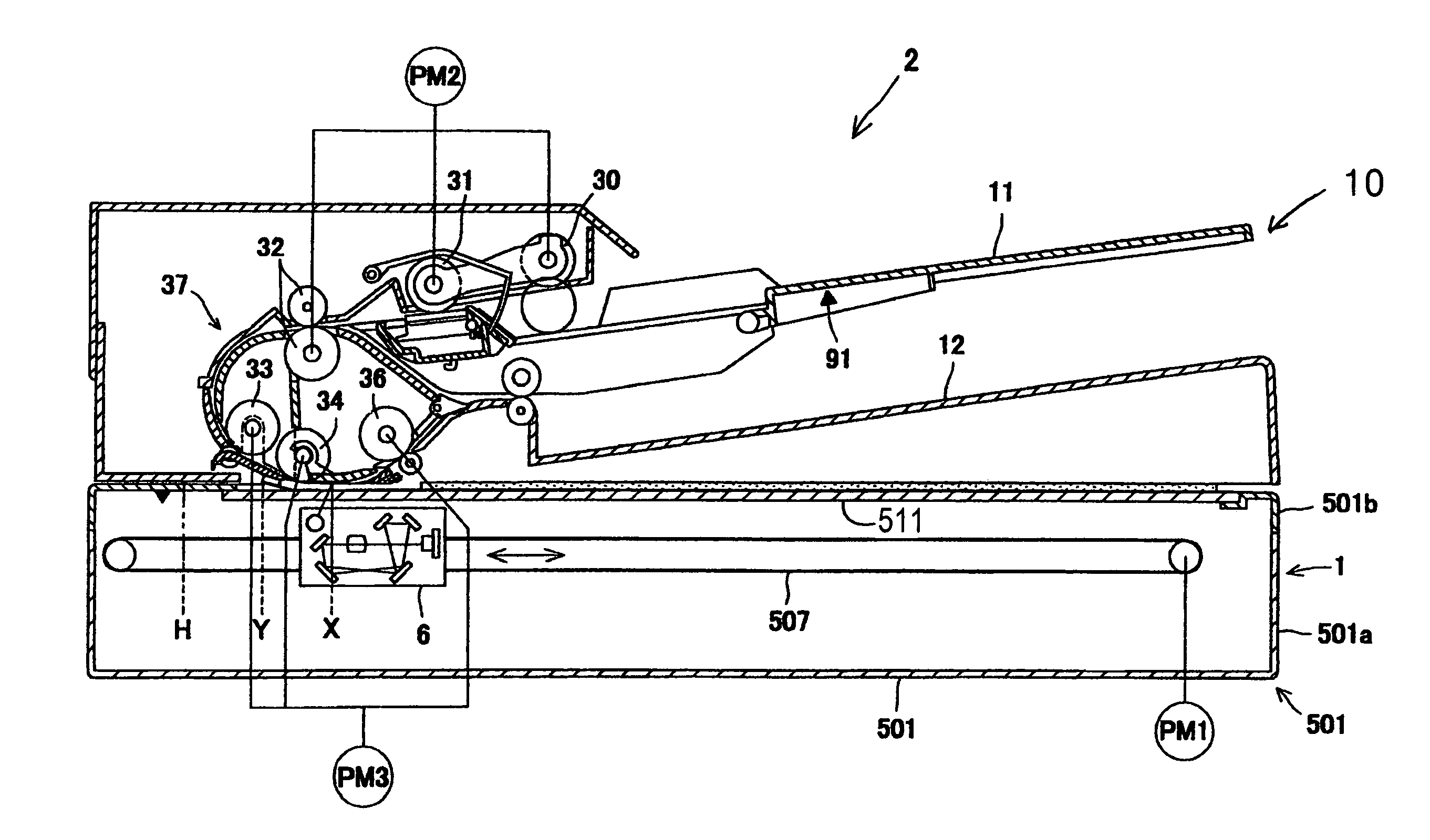
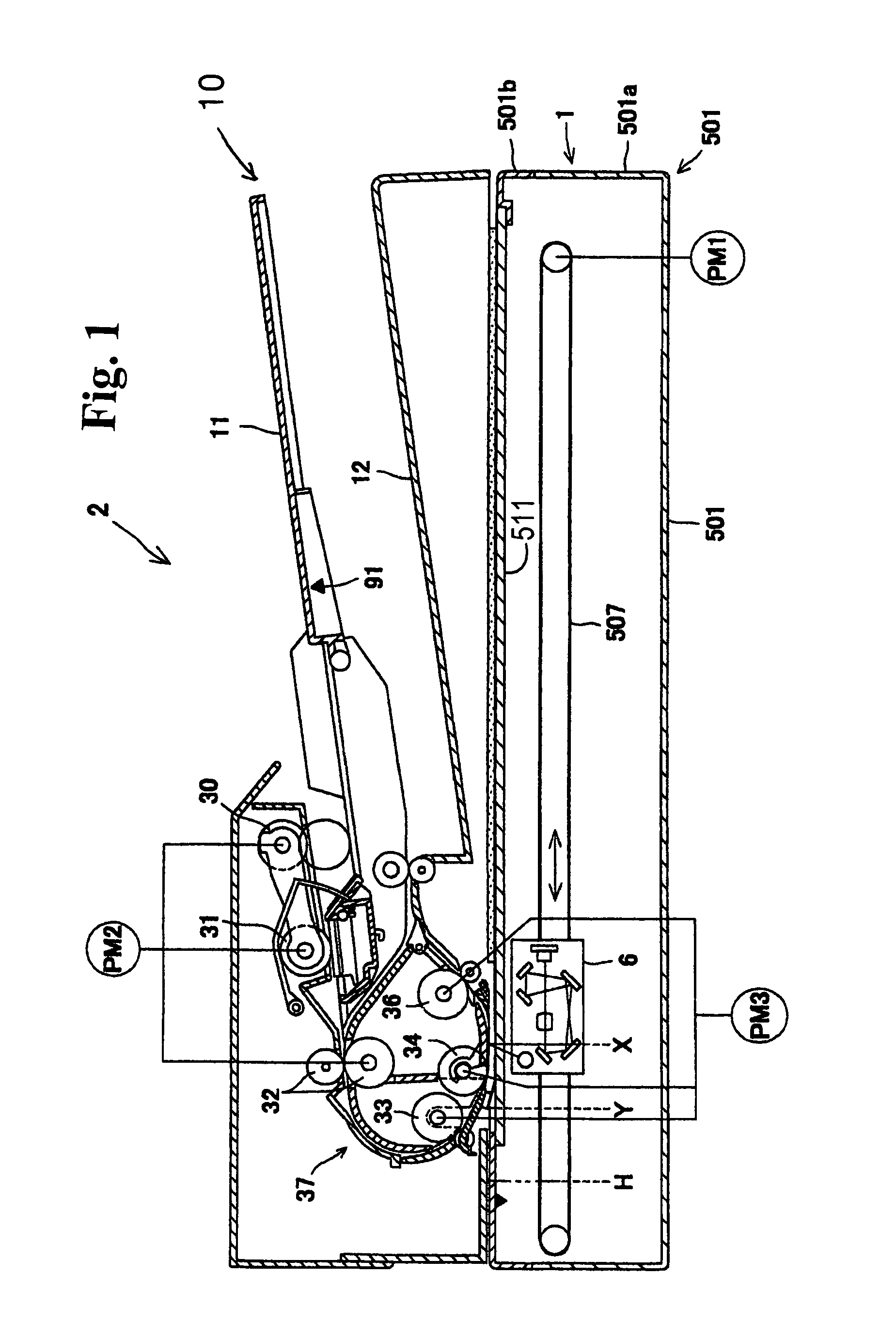
[0041]Hereunder, embodiments of the present invention will be described with reference to the accompanying drawings. As shown in FIG. 1, an image reading apparatus 10 includes an image reading part 1 for reading an image of an original, and an automatic original transporting part 2 disposed above the image reading part 1 for transporting the original one by one to a predetermined position where the image reading part 1 reads the original.

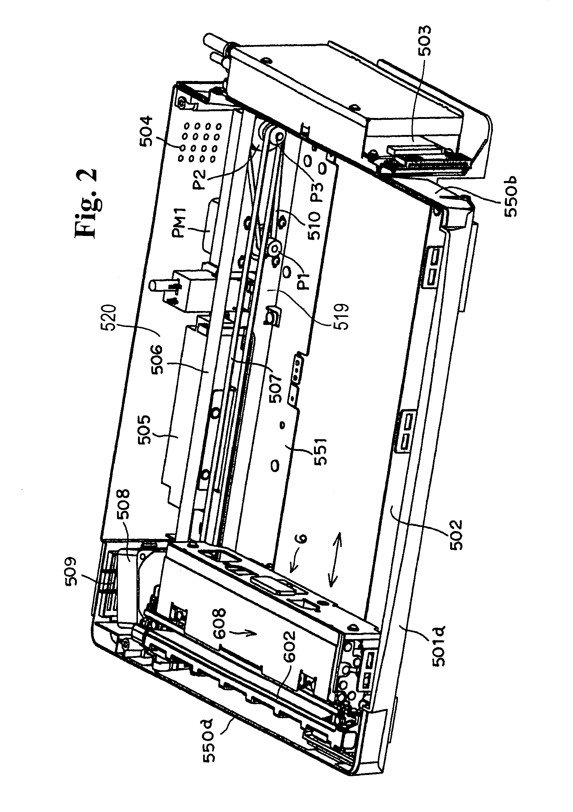
[0042]The image reading part 1 has a box-shaped casing 501 formed of a synthetic resin, i.e. an alloy of acrylic butadiene styrene (ABS) and polycarbonate (PC) having a coefficient of linear thermal expansion of about 80×10−5 ( / ° C.). The casing 501 includes a box-shaped lower casing 501a as a bottom of the casing 501 having an opening in an upper surface thereof and a cover-shaped upper casing 501b disposed above the lower casing 501a. The lower casing 501a has first and second case sidewalls 550a and 550b (see FIG. 2) spaced apart in a longitudina...


PUM


Abstract

An image reading apparatus includes a scanning unit disposed in a box-shaped casing for scanning a stationary original in a sub-scanning direction to read the original; a supporting unit for supporting one side of the scanning unit in a main scanning direction and guiding the one side of the scanning unit in the sub-scanning direction; a driving source for moving the scanning unit in the sub-scanning direction; a drive transmitting unit for transmitting a drive of the driving source to the scanning unit; and first and second reinforcing plates attached to the casing along the sub-scanning direction for reinforcing the casing. The first reinforcing plate forms a guide unit for supporting the other side of the scanning unit in the main scanning direction and guiding the scanning unit in the sub-scanning direction. The driving source and the drive transmitting unit are fixed to the second reinforcing unit.

Description

BACKGROUND OF THE INVENTION AND RELATED ART STATEMENT[0001]The present invention relates to an image reading unit and an image reading apparatus used as a scanner and the like installed in a facsimile device, an image forming apparatus, and a computer.[0002]An image reading apparatus includes an image reading unit having an image sensor such as a CCD mounted in a box shaped casing. The image reading unit is moved in a sub-scanning direction to read an original mounted on a platen fixed to a casing. In the casing, there are provided a driving source such as a motor for driving the image reading unit, a timing belt for transmitting a drive from the driving source to the image reading unit, and a driving system such as a pair of pulleys on which the timing belt is extended.[0003]In recent years, in order to reduce a weight of the apparatus and the number of parts, the casing has been integrally formed with the apparatus. Accordingly, there may be a case that the casing does not have en...

Claims


Application Information

Patent Timeline
IPC IPC(8): G06K7/10H04N1/03H04N1/10H04N1/193
CPCH04N1/03H04N1/0303H04N1/0305H04N1/1017H04N1/193H04N2201/02458H04N2201/02495H04N2201/0246H04N2201/02462H04N2201/02485
Inventor YUI, KENICHI
Owner NISCA KK
Features
  • Generate Ideas
  • Intellectual Property
  • Life Sciences
  • Materials
  • Tech Scout
  • Unparalleled Data Quality
  • Higher Quality Content
  • 60% Fewer Hallucinations
Learn More