Transformer
- Summary
- Abstract
- Description
- Claims
- Application Information
AI Technical Summary
Problems solved by technology
Method used
Image
Examples
first embodiment
[0060] Referring now to FIG. 1 to FIG. 10, a first embodiment of the invention will be described below.
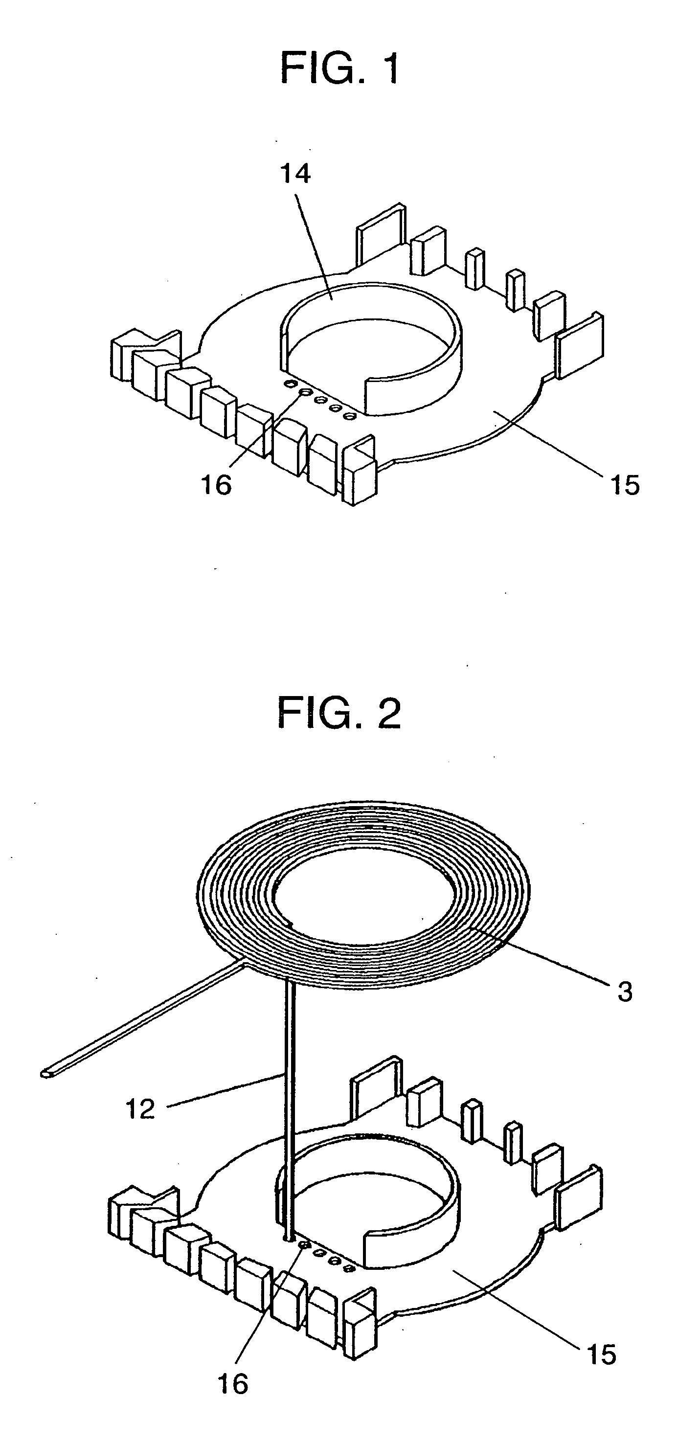
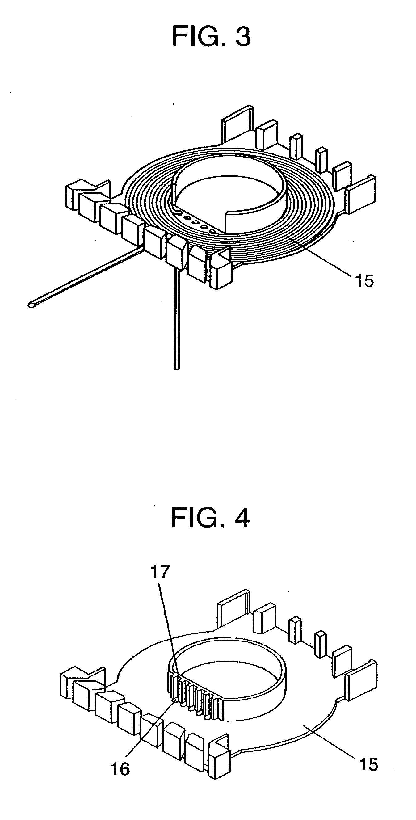
[0061]FIG. 1 is a perspective view of a first bobbin according to the first embodiment of the invention. FIG. 2 shows a state in which a coil-drawn-lead is inserted into a through hole for a drawn lead in the invention when inserting the coil to the first bobbin according to the first embodiment. FIG. 3 is a drawing showing a state in which insertion of the coil to the first bobbin is completed.
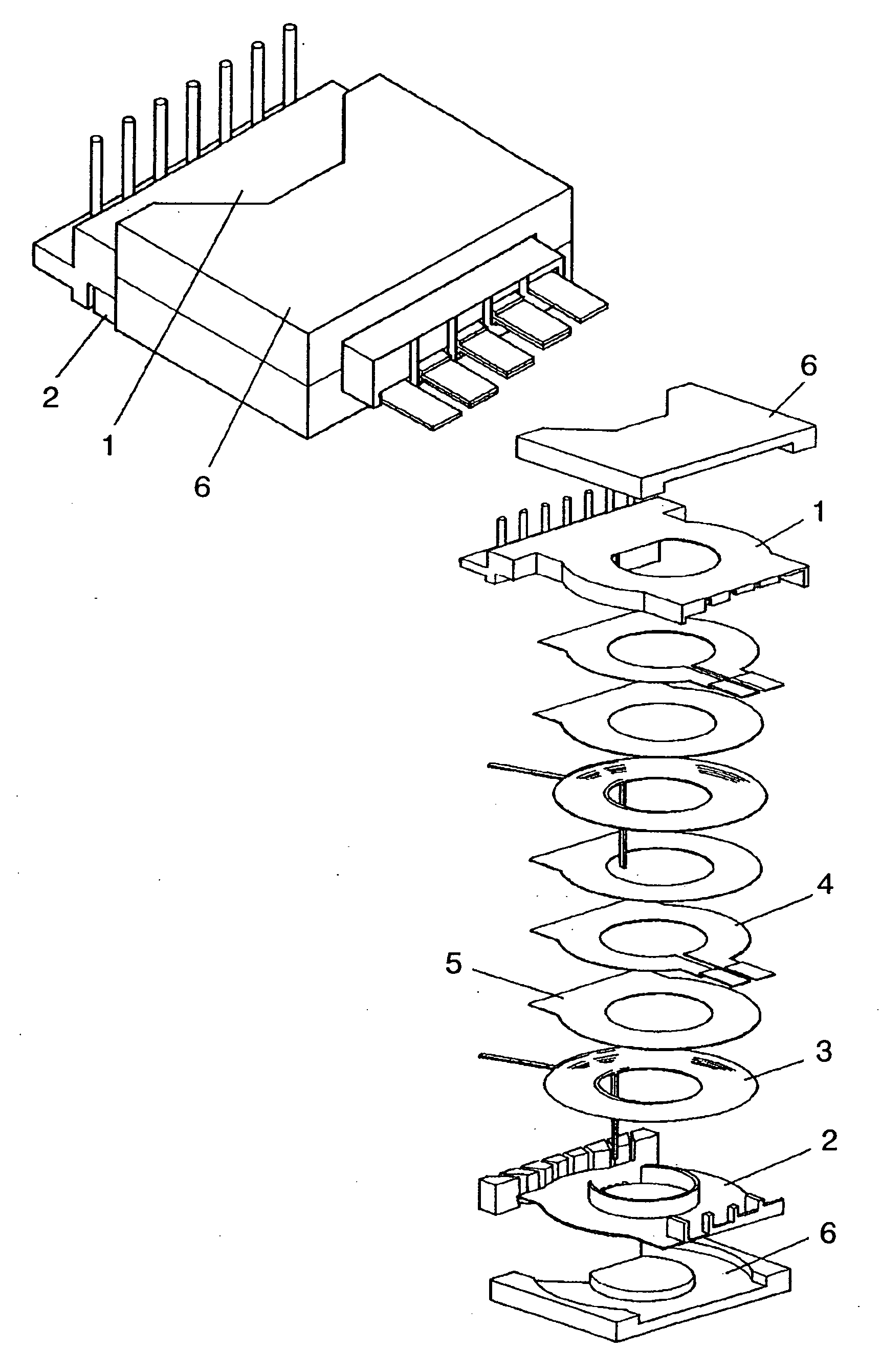
[0062] The transformer in the invention is a transformer in which a coil part including the first bobbin to which the coil is mounted and a second bobbin to be fitted to the first bobbin combined to each other is sandwiched between magnetic cores from above and below. However, in the description and the drawings of the respective embodiments shown below, the second bobbin is omitted. In the description and the drawings shown below, second bobbin 15 is referred to as bobbin 15. First coil 3...
second embodiment
[0070] Referring now to FIG. 11 to FIG. 15, a second embodiment of the invention will be described below.
[0071]FIG. 11 and FIG. 12 are top views of the transformer according to the second embodiment of the invention after the bobbin and the coil are inserted. FIG. 13 is a perspective view of the bobbin of the transformer according to the second embodiment of the invention. FIG. 14 and FIG. 15 are perspective views of the transformer according to the second embodiment of the invention after the bobbin and the coil are inserted.
[0072] In FIG. 13, lead drawing through holes 16 are formed in the vicinity of center leg portion 14 of bobbin 15. FIG. 11 is a top view showing a state after first coil 3 is mounted, FIG. 12 is a top view showing a state after first coil 3 is mounted and then second coil 3a is mounted. FIG. 14 is a perspective view showing a state after first coil 3 is mounted, and FIG. 15 is a perspective view showing a state after first coil 3 is mounted and then second co...
third embodiment
[0073] Subsequently, referring to FIG. 16 to FIG. 19, FIG. 20A, FIG. 20B, FIG. 21A and FIG. 21B, a third embodiment of the invention will be described below.
[0074] In the third embodiment, the effects in the first embodiment and the second embodiment described above are further enhanced. In other words, deformation or damage of the coil-drawn-lead can be avoided even when sandwiching the bobbin in which the coil is inserted by the upper and lower magnetic cores from above and below to finish the transformer. In addition, the possibility of contact between the coil-drawn-lead and the magnetic cores can be avoided, and an insulation distance required by Safety Standard can be secured.
[0075]FIG. 16 and FIG. 18 show the upper magnetic core in this embodiment, and FIG. 17 and FIG. 19 show the lower magnetic core in this embodiment. FIG. 20A is a side view of the transformer in this embodiment in which the magnetic core in FIG. 16 and the magnetic core in FIG. 17 are used, and FIG. 20B ...
PUM
 Abstract
Description
Claims
Application Information
 - R&D
- Intellectual Property
- Life Sciences
- Materials
- Tech Scout
- Unparalleled Data Quality
- Higher Quality Content
- 60% Fewer Hallucinations
Browse by: Latest US Patents, China's latest patents, Technical Efficacy Thesaurus, Application Domain, Technology Topic, Popular Technical Reports.
© 2025 PatSnap. All rights reserved.Legal|Privacy policy|Modern Slavery Act Transparency Statement|Sitemap|About US| Contact US: help@patsnap.com


