Integrated current sensor

a current sensor and integrated technology, applied in the field of electric current sensors, can solve the problems of inconvenient installation, large device height and circuit board area, etc., and achieve the effects of reducing susceptibility to stray magnetic fields and external magnetic noise, high repeatability of current sensors, and tightly controlled

Inactive Publication Date: 2007-09-04
ALLEGRO MICROSYSTEMS INC
View PDF42 Cites 140 Cited by
  • Summary
  • Abstract
  • Description
  • Claims
  • Application Information

AI Technical Summary

Benefits of technology

[0006]In accordance with the present invention, an integrated current sensor is provided with a conductor having a first notch substantially aligned with a second notch, a magnetic field transducer having at least a portion positioned in the first notch, and a magnetic core. The magnetic core is substantially C-shaped, with a central region and a pair of substantially parallel legs extending from the central region. At least a portion of the central region of the magnetic core is positioned in the second notch such that each leg covers at least a portion of a respective surface of the magnetic field transducer. In the illustrated embodiments, the magnetic field transducer is a Hall effect sensor containing a Hall effect element.
[0007]With this arrangement, the Hall effect sensor, the conductor, and the magnetic core are essentially locked in place relative to each other by the first and second notches and also by dimensional characteristics of the elements. As a result of the precise mechanical positioning of the elements, the sensitivity of the current sensor is highly repeatable and thus, tightly controlled.
[0008]The magnetic core provides a sensitivity that is higher than otherwise possible and also provides a magnetic field across the Hall effect element that is substantially uniform.
[0009]In one embo...

Problems solved by technology

Such devices tend to be undesirably large,...

Method used


Image

  • Integrated current sensor
  • Integrated current sensor
  • Integrated current sensor

Examples


Embodiment Construction

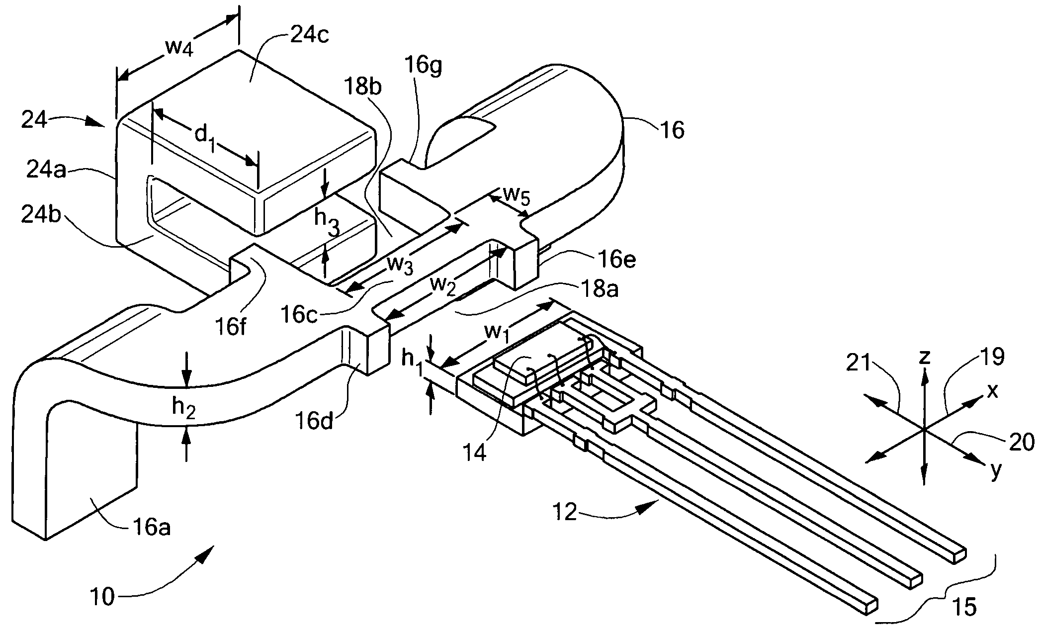
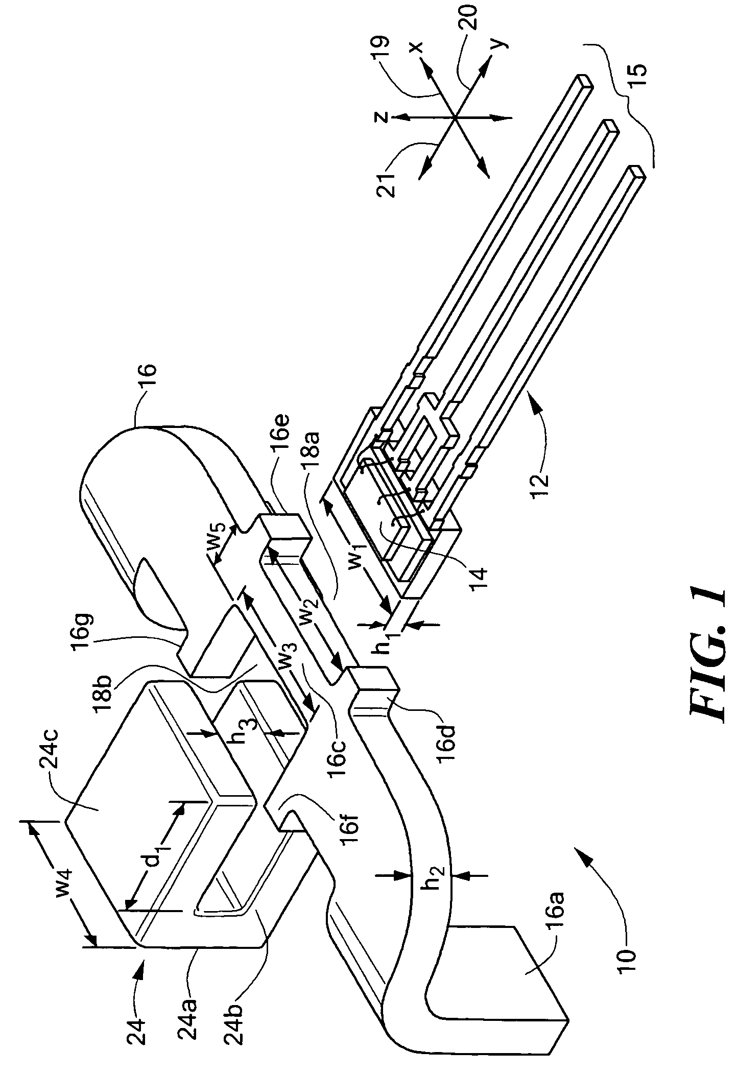
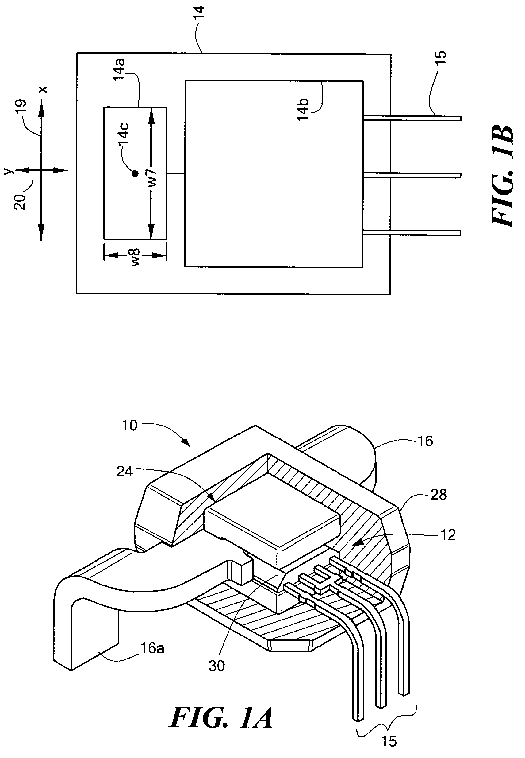
[0026]Referring to FIG. 1, a miniaturized, integrated current sensor 10 includes a magnetic field transducer, here in the form of Hall effect sensor 12, a current-carrying conductor 16 and a magnetic core 24. The conductor 16 includes features for receiving portions of the Hall effect sensor 12 and the magnetic core 24 such that the elements are maintained in a fixed position relative to each other. In the illustrated embodiment, the conductor 16 has a first notch 18a and a second notch 18b substantially aligned with the first notch. In assembly, at least a portion of the Hall effect sensor 12 is disposed in the first notch 18a. The magnetic core 24 is substantially C-shaped and has a central region 24a and a pair of substantially parallel legs 24b, 24c extending from the central region. In assembly, at least a portion of the central region 24a is disposed in the second notch 18b of the conductor such that each leg 24b, 24c covers at least a portion of a respective surface of the Ha...


PUM


Abstract

An integrated current sensor includes a magnetic field transducer such as a Hall effect sensor, a magnetic core, and an electrical conductor. The conductor includes features for receiving portions of the Hall effect sensor and the core and the elements are dimensioned such that little or no relative movement among the elements is possible.

Description

CROSS REFERENCE TO RELATED APPLICATIONS[0001]This application is a continuation of U.S. patent application Ser. No. 10 / 251,007 entitled “INTEGRATED CURRENT SENSOR,” filed on Sep. 20, 2002, now U.S. Pat. No. 6,781,359.STATEMENT REGARDING FEDERALLY SPONSORED RESEARCH[0002]Not Applicable.FIELD OF THE INVENTION[0003]This invention relates generally to electrical current sensors, and more particularly to a miniaturized current sensor having an integrated conductor.BACKGROUND OF THE INVENTION[0004]As is known in the art, one type of conventional electrical current sensor uses a Hall effect magnetic field transducer in proximity to a current-carrying conductor. The Hall effect device generates an output signal having a magnitude proportional to the magnetic field induced by the current through the conductor. Typical current sensors of this type include a gapped toroid magnetic flux concentrator, with the Hall effect device positioned in the toroid gap. The Hall effect device and toroid are...

Claims


Application Information

Patent Timeline
IPC IPC(8): G01R15/20G01R33/07
CPCG01R15/202
Inventor STAUTH, JASONDICKINSON, RICHARDSAUBER, JOHNENGEL, RAYPINELLE, SANDRA
Owner ALLEGRO MICROSYSTEMS INC
Why Eureka
Try Eureka