Magnetic field sensor

a magnetic field sensor and sensor technology, applied in the direction of magnetic field measurement using galvano-magnetic devices, acceleration measurement using interia forces, instruments, etc., can solve the problems of unintentional magnetisation of the ferromagnetic core, insufficient sensitivity, and high cost of the sensor, so as to reduce the size, reduce the cost, and reduce the size of the magnetic field sensor

Inactive Publication Date: 2006-05-02
MELEXIS TECH NV
View PDF10 Cites 147 Cited by
  • Summary
  • Abstract
  • Description
  • Claims
  • Application Information

AI Technical Summary

Benefits of technology

[0007]The invention assumes the principle of a fluxgate sensor as is known, for example, from the above-mentioned article. Fluxgate sensors have an exciter coil, a ferromagnetic core and a read-out coil. They are suitable for the measurement of weak magnetic fields as the magnetic field to be measured is chopped with the aid of the exciter coil and the ferromagnetic core, ie, is periodically switched on and off at the location of the read-out coil. The output signal of the read-out coil can then be evaluated synchronously to the chopping with the lock-in technique. The invention suggests that, for optimising the characteristics of a magnetic field sensor foreseen for the measurement of weak magnetic fields, all processes used in the semiconductor technology are included, ie, all processes from the start of the production of the semiconductor chip on a wafer over the post-processing where the ferromagnetic core is mounted, up to the backend where the semiconductor chip is mounted and encapsulated to the finished magnetic field sensor. This approach enables the use of a ring-shaped ferromagnetic core the advantage of which exists in that it can be magnetically saturated with a minimum of electric current and electrical power. The windings of the exciter coil then preferably consist of conductor tracks and bonding wires. In addition, the invention suggests that Hall elements be used instead of read-out coils because their size can be reduced as desired without loss in sensitivity. Such a magnetic field sensor can be greatly miniaturised.

Problems solved by technology

An important disadvantage of this sensor exists in that an adequate sensitivity has to be taken at the expense of a relatively large ferromagnetic core.
This stands in the way of a further miniaturisation and makes the sensor relatively expensive.
A further problem exists in that the ferromagnetic core can be unintentionally magnetised by an outer magnetic field that is much larger than the actual field to be measured.
The current flowing in the coil is then no longer able to freely align the individual magnetic domains, which leads to a measuring error.

Method used


Image

  • Magnetic field sensor
  • Magnetic field sensor
  • Magnetic field sensor

Examples


Embodiment Construction

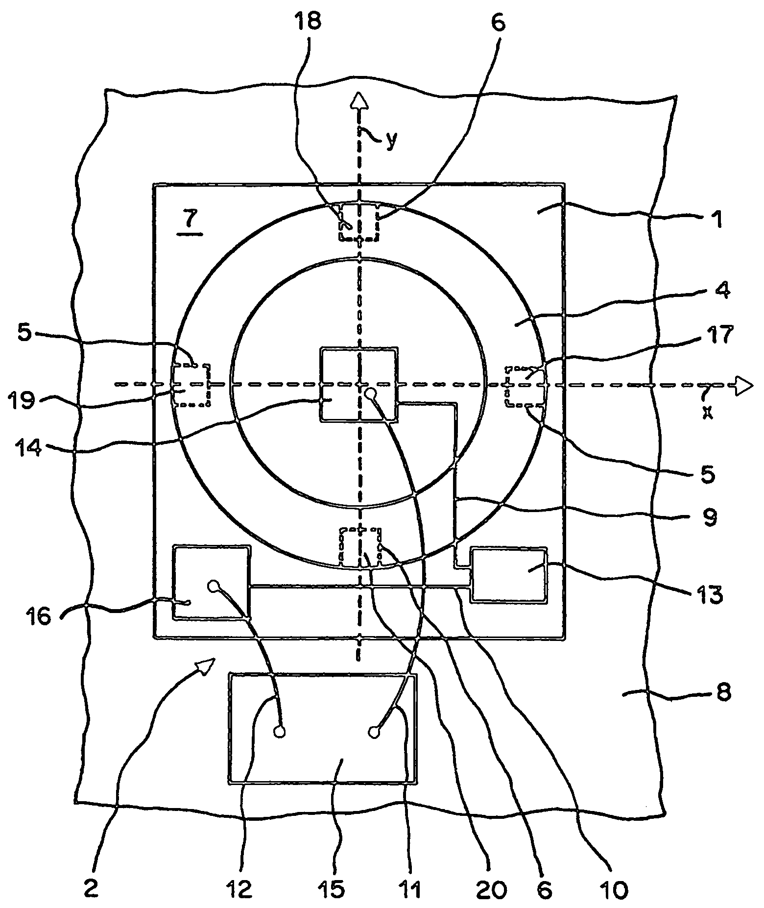
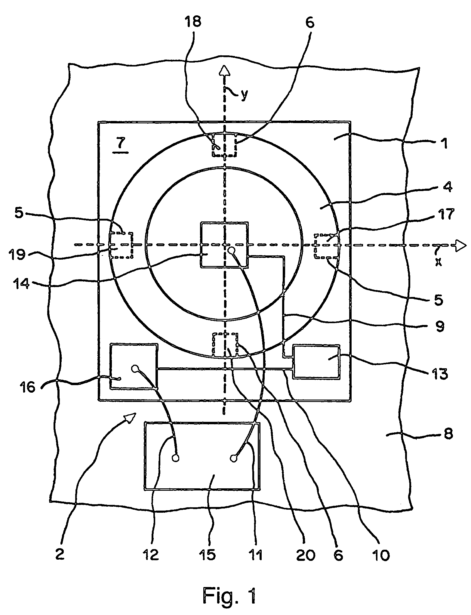
[0018]FIG. 1 shows a plan view of a magnetic field sensor formed as a semiconductor chip 1 for the measurement of two components of a magnetic field. A cartesian x,y,z system of co-ordinates serves as reference system whereby the z direction runs vertically to the drawing plane. The magnetic field sensor comprises an exciter coil 2 with at least one winding to which current is applied, a ring-shaped ferromagnetic core 4, two read-out sensors 5, 6 and an electronic circuit 7. The read-out sensor 5 serves to detect the x component of the magnetic field, the read-out sensor 6 serves to detect the y component of the magnetic field. Preferably, each of the read-out sensors 5, 6 consists of two locally separated but electrically connected sensors. The magnetic field sensor is produced using a technology with which the electronic circuit 7, parts of the exciter coil 2 and the read-out sensors 5, 6 are first manufactured using a standard CMOS technology and then the ferromagnetic core 4 is ...


PUM


Abstract

A magnetic field sensor for measuring at least two components of a magnetic field comprises a ferromagnetic core mounted on a semiconductor chip, an exciter coil to which a current can be applied and two read-out sensors. The ferromagnetic core is ring-shaped. The exciter coil is preferably formed from conductor tracks of the semiconductor chip and from bonding wires.

Description

CROSS REFERENCE TO RELATED APPLICATION[0001]The present application is related to and claims priority of the following co-pending applications, namely, PCT application number PCT / EP02 / 05559 of Sentron AG entitled Magnetic Field Sensor, filed on May 21, 2002; and EP Application No. 01810518.9, filed May 25, 2001. The above-identified applications are incorporated herein by reference in their entirety.FIELD OF THE INVENTION[0002]The invention concerns a magnetic field sensor.BACKGROUND OF THE INVENTION[0003]Such magnetic field sensors are suited for the measurement of magnetic fields the strength of which are only a few nT to mT for example as a compass for measuring the direction of the earth's magnetic field.[0004]A magnetic field sensor of the type named in the preamble of claim 1 is known from EP 1 052 519 A1 as well as from the article “CMOS planar 2D micro-fluxgate sensor” by the authors L. Chiesi, P. Kejik, B. Janossy and R. S. Popovic, which was published in the magazine Senso...

Claims


Application Information

Patent Timeline
Patent Type & Authority Patents(United States)
IPC IPC(8): G01R33/07G01C17/30G01R33/02G01R33/04G01R33/05
CPCG01R33/05
Inventor SCHOTT, CHRISTIANPOPOVIC, RADIVOJERACZ, ROBERT
Owner MELEXIS TECH NV
Why Eureka
Try Eureka