Multiphase voltage regulator having coupled inductors with reduced winding resistance

a voltage regulator and coupled inductor technology, applied in the direction of inductance, dc-dc conversion, power conversion systems, etc., can solve the problems of adversely affecting the energy conversion efficiency, and achieve the effect of preventing magnetic saturation

Inactive Publication Date: 2010-01-19
VIRGINIA TECH INTPROP INC
View PDF7 Cites 145 Cited by
  • Summary
  • Abstract
  • Description
  • Claims
  • Application Information

AI Technical Summary

Problems solved by technology

However, the extra conductor windings required for the coupled inductors increases the DC (ohmic) resistance of the circuit, which adversely affects the energy conversion efficiency.

Method used


Image

  • Multiphase voltage regulator having coupled inductors with reduced winding resistance
  • Multiphase voltage regulator having coupled inductors with reduced winding resistance
  • Multiphase voltage regulator having coupled inductors with reduced winding resistance

Examples


Embodiment Construction

[0025]The present invention provides multiphase voltage converters (e.g. buck converters, boost converters, and buck-boost converters) having coupled inductors with reduced winding resistance. In a conventional, prior art multiphase converter with coupled inductors, the inductors each comprise long electrical conductors wound around a magnetic core. In the present invention, by comparison, the conductors are much shorter and therefore have lower ohmic resistance. Consequently, the energy efficiency of the voltage converter is increased in the present invention. The present coupled inductor design can be used with buck voltage converters, boost voltage converters, and buck-boost voltage converters.

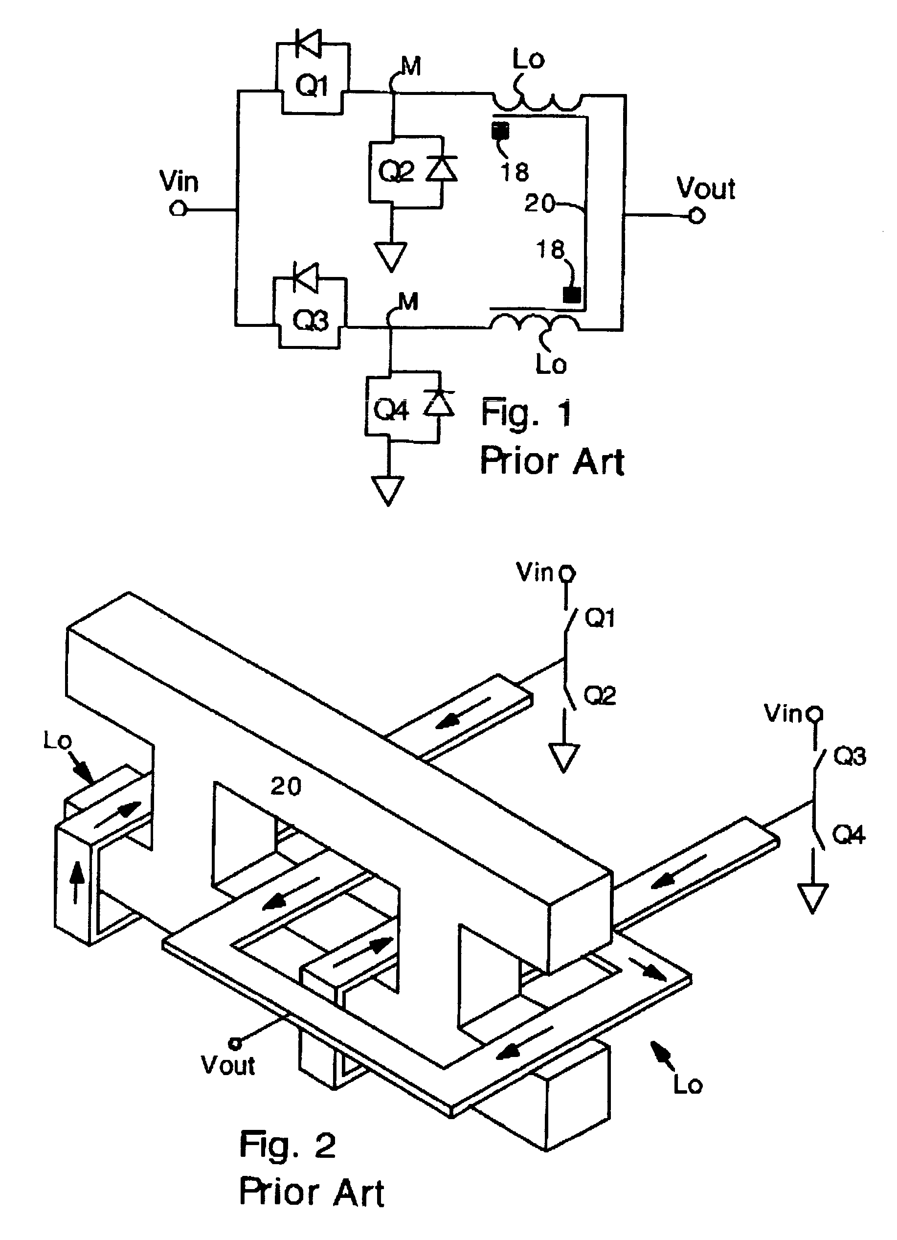
[0026]FIG. 1 shows a schematic diagram of a 2-phase buck converter with coupled inductors Lo according to the prior art. Each phase has two switches Q1 Q2 and Q3 Q4 connected in series between a voltage source Vin and ground. Each pair of switches is connected at a midpoint M. The inductors...


PUM

PropertyMeasurementUnit
angleaaaaaaaaaa
angleaaaaaaaaaa
angleaaaaaaaaaa

Abstract

A multiple phase buck converter or boost converter, or buck-boost converter has an inductor in each phase. The inductors are inversely coupled. In a first embodiment, the converter includes a toroidal magnetic core with inductors extending under and over opposite sides of the toroidal magnetic core. The coupled inductors are thereby inversely coupled and have a relatively low ohmic resistance. In a second embodiment, the converter comprises a ladder-shaped magnetic core (i.e. having parallel sides, and connecting rungs). In this case, the inductors extend under the sides, and over the rungs. Each inductor is disposed over a separate rung. The ladder-shaped magnetic core is preferably disposed flat on a circuit board. Inverse coupling and low ohmic resistance are also provided in the second embodiment having the ladder structure.

Description

FIELD OF THE INVENTION[0001]The present invention relates generally to multiphase voltage regulators (e.g. buck or boost regulators) with an inductor in each phase. More particularly, the present invention provides a coupled inductor design with reduced winding resistance. The present invention employs coupled inductors having reduced electrical resistance.BACKGROUND OF THE INVENTION[0002]Buck converters are commonly used to change the voltage or polarity of a DC power supply. Typically, a buck converter has several phases connected in parallel, with each phase having two switches (top and bottom switches) connected to an inductor. Such multiple phase buck converters are well known in the art and are commonly used for providing regulated DC power for microprocessors, telecommunications electronics and the like.[0003]In recent years it has been discovered that efficiency and transient response of a multiple phase buck converter can be improved by coupling the inductors of several pha...

Claims


Application Information

Patent Timeline
Patent Type & Authority Patents(United States)
IPC IPC(8): H01F27/28
CPCH01F37/00H02M3/1584H01F17/0006H01F27/255
Inventor XU, MINGDONG, YANLEE, FRED C.
Owner VIRGINIA TECH INTPROP INC
Why Eureka
Try Eureka